Do you have a question about the Garmin GTX 45R and is the answer not in the manual?
A warning means injury or death is possible if the instructions are not obeyed.
A caution means that damage to the equipment is possible.
To the maximum extent permitted by applicable law, the licensed software and documentation are provided 'as is'...
Notwithstanding anything to the contrary herein, to the maximum extent permitted by applicable law...
Licensee shall indemnify, defend and hold Garmin and its affiliates harmless against any and all losses...
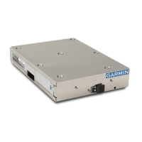
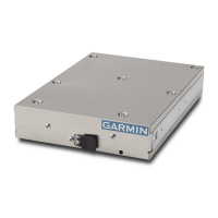
The GTX 35R/45R include ADS-B Out capabilities when installed with GPS position source...
FIS-B information is for pilot-planning and pilot near-term decisions. The information shown are areas of inclement weather...
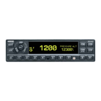
The GTX 35R supplies information about nearby traffic through the FAA provided radar based TIS-A service.
Table 1-4 Transponder Specifications
Table 1-5 UAT Receiver Specifications
Table 1-6 1090 MHz Receiver Specifications
GTX 35R/45R units require an input voltage of between 9 VDC and 33 VDC.
The GTX 35R/45R meets compliance with the TSO(s) when interfaced with equipment and installed in accordance with the requirements...
Table 3-1 GTX 35R/45R Configurations
For the GTX 45R some types of transponder antennas that utilize thin radiator elements are only intended for use at 1030 and 1090 MHz.
GTX Transponder antenna G3X system An appropriate GPS position source
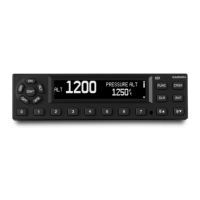
In most installations, the GTX 35R/45R receives pressure altitude data from the G3X system.
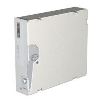
Mounting location considerations for the antenna(s) are provided in this section.
All electrical connections, except for the antenna(s) and shield grounds, are made through the D-sub connectors...
The GTX 35R/45R connector kits include backshell assemblies and ground adapter assemblies.
Table 5-1 P3251 Connector
Table 5-2 P3252 Connector
Examine the wire harness to make sure the connection to aircraft systems and avionics equipment is correct before the unit is energized.
The GTX 35R/45R Installation Tool is used by Garmin dealers to update GTX unit software...
With a Pitot/static test set connected, select the GAE tab under the Sensor tab in the Configuration section.
Use the GTX 35R/45R Install Tool through the USB port to install software on the unit.
| Brand | Garmin |
|---|---|
| Model | GTX 45R |
| Category | Marine Radio |
| Language | English |