EasyManua.ls Logo

Garnet SeeLeveL II 709 Series - User Manual

Garnet SeeLeveL II 709 Series
18 pages
Print Icon
To Next Page IconTo Next Page
Loading...
Page 1SeeLeveL II 709 Series Display Manual
HOLDING TANK MONITORS
CANADA
Garnet Instruments
286 Kaska Road
Sherwood Park, AB T8A 4G7
USA
Garnet US Inc.
5360 Old Granbury Road
Granbury, TX 76049
Through decades of experience and development the SeeLeveL tank
monitor series has established itself as the gold standard in level
measurement technology for the Recreational Vehicle industry.
The SeeLeveL II™ has a combination of features, accuracy, reliability, and
diagnostic capability that provide the best possible user experience.
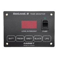
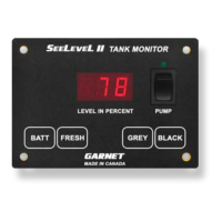
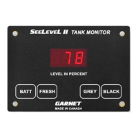
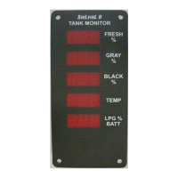
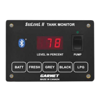
Depending on the model, the SeeLeveL II monitors battery voltage, and
displays percentage of full readouts for FRESH, GREY, GALLEY, and BLACK
tank levels. In addition, the system can display the operating characteristics
of each of the tank sending units, giving it unsurpassed diagnostic
capability.
INTRODUCTION
709 Series Manual_v1.0 - 21-Oct-2022
DISPLAY INSTALLATION GUIDE
& USER MANUAL FOR 709 SERIES
709-2P | 709 | 709-P3 | 709-P3W | 709-HP3W
709-BTP3
| 709-RVC | 709-RVC PM | 709-RVC NLP
709-N2K NLP
| 709-4 | 709-4P | 709-4LP
Document the following information for future reference. See page 4 for
more information.
Model Number: ___________________________________________________________
Serial Number: ____________________________________________________________
Date of purchase: _________________________________________________________

Questions and Answers

Summary

INTRODUCTION

SeeLevel II Tank Monitor Overview

Introduces the SeeLevel II tank monitor series, highlighting its role as a gold standard in RV level measurement technology.

Model Series Identification

Lists the various 709 series models available, assisting users in identifying their specific unit.

User Reference Information

Provides fields to document Model Number, Serial Number, and Date of Purchase for future reference.

SAFETY INFORMATION

Understanding Safety Symbols and Alerts

Explains the meaning of safety symbols like NOTE, CAUTION, and WARNING used throughout the manual to highlight potential hazards.

Critical Electrical Safety Precautions

Emphasizes the necessity of fused power circuits and potential relays for pump or heater switches to prevent damage.

SYSTEM COMPONENTS AND FEATURES

Sender Technology and Diagnostics

Details sender panels, their installation, auto-calibration, and diagnostic capabilities for tank health monitoring.

Display Unit and Battery Monitoring

Explains how the display unit shows tank levels and battery voltage with specific resolutions and updates.

Connectivity Options

Covers optional features like LPG sensors, Bluetooth connectivity, RV-C, NMEA 2000, and alarm outputs.

INSTALLATION INFORMATION

Model Feature Comparison

Presents a table comparing features across different 709 series models, aiding in understanding capabilities.

Installation Resources and Tools

Lists required tools and equipment, and directs users to download additional documentation for installation.

DISPLAY INSTALLATION GUIDE

Mounting Template and Cutout Dimensions

Provides a template with exact dimensions for cutting a hole in the RV wall to mount the display panel securely.

Display Wiring and Grounding

Guides on connecting the display wiring, emphasizing proper grounding to the breaker panel for reliable operation.

OPERATION GUIDE

Reading Tank Levels

Instructions on how to press tank buttons to view level percentages and use double-press for continuous monitoring.

Checking Battery Voltage

Explains the simple process of pressing the BATT button to display the current battery voltage reading.

Reading LPG Tank Levels

Details how to check the LPG tank level, including options for continuous display and holding the reading.

COMMUNICATION PROTOCOLS

RV-C Bus Integration

Explains RV-C as a CAN-based protocol for control and diagnostics, detailing connector pinout and sender source addresses.

NMEA 2000 Network Connectivity

Describes NMEA 2000 compatibility for the 709-N2K model, providing its report format and connector pinout.

CONFIGURATION GUIDE

Setting Display LED Brightness

Procedure to adjust the brightness of the display LEDs to suit ambient light conditions.

Configuring Tank Sender Count

Steps to program the number of senders per tank, ensuring accuracy and proper system function.

CALIBRATION AND SETTINGS

LPG Sender Calibration Procedure

Guide to calibrate the LPG sender accurately, requiring the LPG tank to be full before starting the process.

Tank Capacity Configuration

Instructions for setting tank capacity in US gallons for specific models (709-N2K NLP).

Battery Voltage Recalibration

Details the process for recalibrating the battery voltage display, requiring a specific input voltage for accuracy.

BLUETOOTH MODEL CONFIGURATION

Programming Tank Alarm Set Points

Steps to enter alarm programming mode to set alarm points for each tank and test alarm functions.

Alarm Logic and Polarity Settings

Explains settings for trip polarity, common alarm output inclusion, and failure polarity for LPG.

DISPLAY MODE AND SYSTEM SETTINGS

Primary vs. Secondary Display Setup

Procedure to set a display as primary or secondary for dual-display systems to manage sender requests and alarms.

LPG Sender Enable;Disable Function

Instructions on how to enable or disable the LPG sender using the primary display.

Hardware;Software Revision Check

Guidance on checking the display's hardware and software revision versions.

TROUBLESHOOTING GUIDE

Interpreting Display Error Codes

Lists common display error codes, their potential causes, and recommended solutions for troubleshooting.

Sender Diagnostics and Signal Power

Explains sender diagnostics, including signal power and sender height, for checking sender health and performance.

DIAGNOSTIC PROCEDURES

Checking Signal Power and Sender Height

Steps to check signal power percentage and sender height (segment count) for diagnostic purposes.

RV-C Bus Diagnostic Messages

Provides a table of Failure Mode Identifiers (FMI) for messages broadcast over the RV-C bus.

WIRING DIAGNOSTICS

Troubleshooting Open Circuits

A flowchart to diagnose and resolve issues related to open circuits in the sender wiring system.

SHORT CIRCUIT DIAGNOSTICS

Identifying and Resolving Short Circuits

A flowchart to diagnose and fix short circuits in the sender wiring, including steps for isolation and repair.

TROUBLESHOOTING AND INSTALLATION TIPS

System Performance and Accuracy Issues

Addresses system unresponsiveness, erratic operation, and inaccurate readings, offering solutions.

Tank Geometry and Environmental Factors

Discusses how tank shape, metal proximity, and sender placement affect readings and performance.

Tank Cleaning for Optimal Readings

Recommends tank cleaning methods and chemicals to resolve level indication issues caused by buildup.

INSTALLATION AND OPERATIONAL TIPS

Tank Wall Thickness and Sender Placement

Guidance on dealing with thick tank walls and optimal sender positioning for accurate level readings.

Sender Protection and Mounting Safety

Tips on protecting senders from road debris and avoiding display damage during installation.

Electrical Protection and Current Management

Advice on preventing damage from excessive current to the display and pump switch circuits.

WARRANTY AND SERVICE INFORMATION

Warranty Coverage and Limitations

Outlines the hardware warranty, disclaimers, limitations, and procedures for warranty claims.

Obtaining Support and Contact Information

Provides contact details for Garnet Instruments in Canada and the US for service and support inquiries.

Overview

The SeeLevel II™ is a series of holding tank monitors designed for Recreational Vehicles, providing accurate and reliable level measurement for various tanks.

Function Description

The SeeLevel II system monitors tank levels (Fresh, Grey, Galley, Black, and LPG), battery voltage, and offers diagnostic capabilities. It uses flexible self-adhesive sender panels attached to the side of holding tanks, which auto-calibrate to the tank's height. The display unit receives information from these senders via a two-conductor wire and shows levels in percent on a 3-digit LED display.

Tank Level Monitoring:

  • Displays levels for Fresh, Grey, Galley, and Black tanks from 0% to 100%.
  • LPG (if equipped) uses an existing electrical sender and shows levels from 0% to 100%.
  • Continuous display mode is available, indicated by a decimal point on the right, updating once per second. This mode automatically shuts off after 5 minutes or can be manually ended.

Battery Voltage Monitoring:

  • Measures RV battery voltage with a resolution of 0.1 volt.
  • The display shows the battery level in volts.

Diagnostic Capabilities:

  • Senders transmit diagnostic information to detect sludge buildup, damage, or delamination.
  • Error codes are displayed for wiring issues (disconnected, shorted, cut) or defective sender panels.
  • Sender diagnostics include "Sender signal power" (indicating signal strength through the tank wall) and "Sender height" (number of receive segments).

Connectivity (Model Dependent):

  • Bluetooth®: Allows checking tank levels, battery voltage, and LPG levels on compatible smartphones/tablets via a free app. Includes one programmable alarm output.
  • RV-C Bus Communication: Compatible with RVs having an RV-C network. Senders use default source addresses (72 for tanks, 73 for LPG) and SPN-ISB instances. Includes one programmable alarm output.
  • NMEA 2000 Network: Model 709-N2K NLP is NMEA 2000 compatible, making tank levels and capacity available on the NMEA Bus. Reports as NMEA device class 75 (sensor communication interface) with function code 150 (fluid level).

Alarm Output (If equipped):

  • A single common alarm output can be programmed to indicate high/low sewage, water, or LPG levels.
  • Multiple alarms can be assigned to the output.
  • The alarm can be connected to an indicator light or used to prevent toilet use when the black tank is full.

Important Technical Specifications

  • Display: 3-digit LED, showing 0-100% for tank levels and 0.1V resolution for battery.
  • Sender Type: Flexible self-adhesive printed circuit board.
  • Sender Stacking: Multiple senders can be double-stacked for tank heights from 4" to 25".
  • Power Circuit: All power circuits must be fused. Maximum current rating for pump switch is 7.5 amps (some models 10 amps), heater switch 10 amps. Relays may be required for higher amperage pumps/heaters.
  • RV-C Connector: 4-pin connector (Open, CAN-Hi, CAN-Lo, Ground).
  • NMEA 2000 Connector: 4-pin connector (+Voltage, CAN-Hi, CAN-Lo, -Voltage).
  • Manufacturer Code (NMEA 2000): 873.
  • Product Code (NMEA 2000): 15197.
  • NMEA Database Version: 2.200.

Usage Features

Operation:

  • Reading Levels: Press the corresponding tank button (FRESH, GREY, BLACK, LPG) or BATT button. The display shows the level for about 5 seconds before shutting off.
  • Continuous Display: Press a tank button twice to enter continuous display mode.
  • Holding Display: Hold the BATT or LPG button to continuously display the reading.

Configuration:

  • LED Brightness: Adjustable from minimum (b-1) to maximum (b-4) by holding BATT and GREY (or BLACK for 709-2P) buttons.
  • Number of Senders: Programmed by holding the tank button and BATT button. Options are 0, 1, or 2 senders per tank (0 senders remove tank from RV-C/Bluetooth data).
  • LPG Sender Calibration: Requires the LPG tank to be full. Hold LPG and BATT buttons until "CAL" is displayed.
  • Tank Capacity (709-N2K NLP only): Programmed by holding the tank button and BATT button. Displays capacity in US gallons, adjustable with GREY (increase) and FRESH (decrease) buttons.
  • Battery Voltage Calibration: Requires a 13.0 Vdc supply. Hold BATT button while applying power.
  • Alarm Set Points (Bluetooth models only): Programmed by holding the tank button and BATT button. Allows setting high/low alarm points (0-99%), trip polarity (high/low level), and inclusion in common alarm output.
  • LPG Failure Polarity (if equipped with LPG): Configurable as "fail to full" (FEF) or "fail to empty" (FEE) by holding the LPG button.
  • Primary/Secondary Display Mode: Configurable for dual display systems to avoid reading errors. Primary display initiates scanning, secondary passively listens. Alarms are inactive on secondary displays.
  • Enable/Disable LPG Sender (RVC and Bluetooth models only): Hold LPG and BATT buttons until "En" (enabled) or "dIS" (disabled) is shown, then toggle with LPG button.
  • Hardware/Software Revision Check: Hold BATT and FRESH buttons to display version number (e.g., "4.10").

Maintenance Features

Troubleshooting Guide:

  • Error Codes:
    • OPN (Open circuit): Sender unresponsive, open circuit in wiring, or sender not connected.
    • Sht (Short circuit): Blue communication wire shorted to ground.
    • Err (Error): Signal corruption due to bad wiring, bad senders, or multiple senders programmed the same.
    • SEr (Stacked senders): Display programmed for single sender but double-stacked senders connected.
    • ntP (No top sender): Programmed for double-stacked but only bottom sender reporting.
    • nbO (No bottom sender): Programmed for double-stacked but only top sender reporting.
    • CAL (Calibration failure): Memory failure for battery voltage or tank sender signal values.
  • Sender Diagnostics:
    • Signal Power: "P" followed by a number (e.g., P26 for 26%). Typical is 50-60%, minimum 20%. POO is 100%. Low power indicates detached sender, sludge buildup, bad wiring, low battery, or defective sender.
    • Sender Height: "h" followed by a number (e.g., h 6 for 6 segments). Indicates the number of receive segments. Fewer segments than expected means sender needs cutting or replacement.
  • Wiring Diagnostics Flowcharts: Detailed steps for diagnosing open and short circuits in sender wiring.
  • RV-C Diagnostics: FMI (Failure Mode Identifier) table for messages broadcast over the RV-C bus (DIS or OFF, ERR, BOT, TOP, NTP, NBP, SIN, OPN, SHT).

Troubleshooting & Installation Tips:

  • System Freezes/Unresponsive: Reboot by cycling 12V power.
  • Erratic/Stopped Operation: Ensure solid wiring connections (use crimp-on butt connectors or solder, not spade connectors).
  • Dual Display Discrepancies: Ensure both console and sender grounds are connected to a common ground circuit, not relying on metal chassis.
  • Readings Jump/Inaccurate:
    • Check for 120VAC interference from nearby wiring.
    • Ensure proper grounding of senders and consoles.
    • Residual/Non-zero water level: May be due to convex/sloped tank bottoms. Reposition sender (raise for convex, measure opposite drain for sloped).
    • Metal Proximity: Keep metal objects (frame, brackets, pipes) at least 2" away from the sender face.
    • Tank Wall Thickness: Excessive thickness (>3/8") can cause zero readings.
    • Sender Position: Ensure sender top is 1/4" to 1/2" from tank top (allowing for wall thickness) for 100% reading.
    • Sludge Buildup: Clean black/grey tanks with RV liquid chemicals (e.g., Tissue Digester, Sensor Cleaner, Happy Campers Holding Tank Extreme Cleaner) if levels are inaccurate when empty.
  • Sender Delamination: Ensure proper tank surface preparation (clean with alcohol/acetone, smooth surface, warm tank if <60°F). Support wiring harness to prevent pulling on sender.
  • Protecting Senders: Apply auto body undercoat (e.g., 3M Professional Grade Rubberized Undercoating) to exposed senders. Avoid lacquer, enamel, or plastic paints.
  • Display Mounting: Ensure smooth, adequately sized cutout in panel. Use non-conductive mounting spacers if mounting to metal to prevent short-circuiting.
  • Pump/Heater Switch Protection: Adhere to current limitations (7.5A/10A). Install appropriate fuses (7.5A automotive style) on +12V red wire if not provided. Use relays for high-drain pumps.

Warranty & Service:

  • One-year warranty on hardware for defects in material and workmanship under normal use.
  • Warranty claims require contacting the installation dealer or Garnet Instruments directly for a Returned Material Authorization (RMA) number.
  • Returns must be freight prepaid. Repaired or replaced at Garnet's discretion.

Garnet SeeLeveL II 709 Series Specifications

General IconGeneral
BrandGarnet
ModelSeeLeveL II 709 Series
CategoryTank Equipment
LanguageEnglish

Related product manuals