EasyManua.ls Logo

Garnet SeeLevel II User Manual

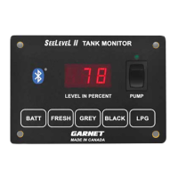
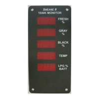
Garnet SeeLevel II
52 pages
To Next Page IconTo Next Page
Page #1 background imageLoading...
Page #1 background image
Printed in Canada
www.garnetinstruments.com
IMPORTANT OPERATOR INFORMATION
DATE INSTALLED: _____________________________________________________________
SERIAL NUMBER: _____________________________________________________________
Signal Level Sender Height
Black Water Tank
Grey Water Tank
Fresh Water Tank
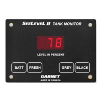
SEELEVEL II
TM
Tank Monitor
MODEL 709-BTP3
MANUAL

Table of Contents

Questions and Answers:

Garnet SeeLevel II Specifications

General IconGeneral
BrandGarnet
ModelSeeLevel II
CategoryMeasuring Instruments
LanguageEnglish

Summary

Important Operator Information

Chapter 1: Overview

Power Circuit Safety Precautions

Details essential safety precautions regarding power circuits and fuse requirements for the system.

Chapter 2: System Description

Sender Panel Functionality and Types

Explains the functionality, technology, and types of sender panels used in the SeeLevel II system.

Display Unit Operation and Features

Details the display unit's operation, button functions, and how it shows tank levels and diagnostics.

Chapter 3: Operating Instructions

How to Read Tank Levels

Provides step-by-step instructions on how to view water and sewer tank levels using the display buttons.

How to Check LPG Tank Level

Explains how to check the LPG tank level using the display and notes limitations.

How to Read Battery Voltage

Details how to check the RV battery voltage using the battery button on the display unit.

Chapter 4: Garnet RV App Instructions

Garnet RV App Overview and Capabilities

Introduces the Garnet RV App, its wireless capabilities, and compatibility with smartphones and tablets.

Garnet RV App System Requirements

Outlines the necessary Android and Apple iOS versions and Bluetooth requirements for the Garnet RV App.

Downloading and Installing the Garnet RV App

Guides users on how to download and install the Garnet RV App from the Google Play Store or Apple App Store.

Enabling Bluetooth for App Connection

Provides instructions for enabling Bluetooth on both Android and Apple iOS devices for app connectivity.

Launching the Garnet RV App Initial Screen

Shows the initial screen of the Garnet RV App upon launching and notes version number variations.

Configuring Garnet RV App Settings

Explains how to access and modify user settings within the Garnet RV App on both Android and iOS devices.

Selecting Sensors to Display in the App

Guides users on selecting which tank sensors to display in the Garnet RV App and customizing text appearance.

Finding and Connecting to Your RV in the App

Instructs users on how to find and select their RV within the Garnet RV App for connection.

Garnet RV App Main Display Overview

Describes the main display screen of the Garnet RV App, showing tank levels and providing access to other functions.

Naming Your RV within the App

Explains how to name the RV within the app for easier identification and personalized display.

Naming Your RV in the Garnet RV App

Details the process of entering a custom name for the RV in the app on both Android and iOS devices.

Saving Your RV Name Entry

Covers saving or canceling the RV name entry and specifies the maximum character limits for Android and iOS.

Troubleshooting: No Garnet RV Devices Found

Troubleshooting: No Sensor Data Displayed

Troubleshooting: Incorrect Use of Demo Mode

Chapter 5: Display Calibration Procedures

Calibrating the LPG Tank Sender

Step-by-step guide to calibrate the LPG sender, emphasizing the need for a full tank during the process.

Enabling and Disabling the LPG Sender

Details how to enable or disable the LPG sender function using specific button combinations on the display.

Adjusting Display LED Brightness Settings

Instructions for adjusting the brightness of the display's LED screen based on usage environment.

Programming the Number of Tank Senders

Explains how to set the number of senders (single, dual) for each tank, typically done during installation.

Setting Tank Alarm Points and Outputs

Guide on setting alarm points for various tank levels (low/high) and configuring common alarm output features.

Configuring Alarm Trip Polarity

Explains how to set alarm trip polarity for high or low level alarms and their behavior.

Including Alarms in Common Alarm Output

Describes how to include or exclude specific tank alarms in the common alarm output.

Setting Sender Failure Polarity

Explains how to configure the system's response to sender failure (fail-to-full or fail-to-empty).

Setting Display Mode: Primary or Secondary

Instructions for setting a display unit as primary or secondary in a dual-display system configuration.

Verifying Primary/Secondary Display Mode

How to verify the current primary or secondary mode setting of the display unit.

Checking Hardware and Software Revisions

Procedure to check the hardware and software version numbers of the display unit.

Chapter 6: Sender Programming Details

Programming 710ES/710SS Senders for Tank Type

Details how to program 710ES/710SS senders for fresh, grey, or black tanks by cutting specific tabs.

Programming 710ES/710SS Senders for Position

Explains programming 710ES/710SS senders for single, top, or bottom sender configurations using tab cuts.

Programming 710JS Senders for Tank Type

Guides on programming 710JS senders for fresh, grey, or black tanks using tab cuts on the sender.

Chapter 7: Installation Guide

Wire Colors and Connector Functions

Table detailing wire colors and their corresponding functions for connecting the system components.

Sender Mounting Location Guidelines

Guidance on selecting optimal locations for sender mounting on tanks, considering surface and clearance.

Sender Options Based on Tank Height

Table outlining sender options (JS, ES, SS) based on tank height and resolution for single/dual sender applications.

Cutting Senders for Single Applications

Specific instructions for cutting and applying single senders, including minimum length requirements.

Cutting Senders for Double Stacked Applications

Guidance for cutting and applying double stacked senders, including length calculations and spacing.

Wiring Senders and Ground Connections

Instructions for wiring the blue signal wires from senders to the display and ensuring proper ground connections.

Final System Calibration and Testing

Covers final steps of calibration, initial testing, and verifying system operation after installation.

Pump Switch Power Rating and Fuse Warning

Important safety warning regarding the pump switch rating and the need for a relay and fuse.

Chapter 8: Troubleshooting Guide

Interpreting Display Trouble Codes

Lists and explains various error codes displayed by the unit, indicating sender or wiring issues.

Diagnosing Wiring Shorts, Opens, and Sender Issues

Methods for diagnosing wiring shorts or opens, and sender issues using the display's troubleshooting features.

Reviewing Sender Diagnostics: Signal Power and Height

Explains how to access and interpret sender signal power and height diagnostics for troubleshooting.

Sender Height Confirmation Diagnostics

Details how sender height is measured and used to confirm auto-calibration and sender length.

Tips for System Freezes and Erratic Operation

Provides tips for resolving system freezes, erratic operation, and discrepancies in dual console systems.

Troubleshooting Inaccurate or Jumping Readings

Addresses causes of inaccurate or jumping readings, such as AC interference and grounding issues.

Resolving Non-Zero Tank Levels When Drained

Explains why a drained tank might show a non-zero level and how to resolve it with sender positioning.

Impact of Nearby Metal on Sender Readings

Discusses how nearby metal objects can affect sender readings and how to mitigate this.

Optimizing Fresh Tank Sender Positioning

Advice on positioning fresh tank senders to ensure maximum usable water is accounted for by the system.

Addressing Issues with Tank Buildup

Addresses tank buildup issues affecting readings and suggests cleaning methods and chemicals.

Troubleshooting Zero or Incomplete Tank Level Readings

Troubleshooting steps for systems that consistently read zero or fail to reach 100% tank level.

Resolving Sender Delamination Problems

Explains causes of sender delamination and proper surface preparation and installation techniques.

Protecting Senders from Road Spray and Debris

Recommendations for protecting senders from road spray and debris using undercoating materials.

Preventing Display Damage During Mounting

Advice on safely mounting the display unit to prevent physical damage or short circuits.

Avoiding Display/Pump Damage from Excessive Current

Warns about excessive current damaging the display or pump switch and outlines fuse/relay requirements.

Chapter 9: Technical Specifications

Sender Resolution, Accuracy, and Materials

Details the resolution specifications for different sender types (JS, ES, SS) and the system's typical accuracy.

Sender Length Ranges and Mounting Panel Specs

Provides sender length ranges, materials used, and specifications for mounting the display panel.

System Power, Wiring, and LPG Requirements

Details power, wiring, LPG sender requirements, and pump switch rating.

Common Alarm Output Specifications

Specifies the voltage, current, and polarity of the common alarm output signal.

Chapter 10: Service and Warranty Information

Hardware Warranty Disclaimer and Coverage

Outlines the standard one-year warranty and limitations on Garnet Instruments' hardware.

Warranty Limitations and Return Procedures

Details warranty limitations, the process for returns, and how to obtain service or replacement.

Related product manuals