Do you have a question about the Gavita Master EL2 and is the answer not in the manual?
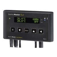
Provides an overview of the Gavita Master controller EL2, its capabilities and dual-channel operation.
Defines essential terms used within the manual for clarity and understanding.
Explains the meaning of warning and caution icons to ensure safe operation.
Lists basic details like product name, code, and manufacturer for the controller.
Details controller dimensions, weight, power, voltage, cable length, and ballast capacity.
Specifies the operating temperature range and humidity limits for the controller.
Lists necessary tools for mounting and cable modifications.
Identifies and lists all components included with the Gavita Master controller EL2.
Explains the function of each button on the controller's interface for navigation.
Details the meaning of LED indicators and their functions on the controller.
Illustrates and describes the various ports and connection points on the controller.
Lists available accessories for the controller, such as cables and splitters.
Specifies compatibility with all Gavita e-series ballasts.
Guides on selecting an appropriate location and mounting the controller securely.
Explains how to install and connect temperature sensors for monitoring climate conditions.
Details connecting a single temperature sensor for 'Follow mode' operation.
Outlines connecting two temperature sensors for 'Inverse mode' operation.
Instructions for connecting the controller to Gavita ballasts and fixtures.
Step-by-step guide for connecting remote ballasts using RJ cables.
Details connecting complete fixtures, including RJ14 splitters.
Explains the process and precautions for shortening RJ cables.
Instructions for connecting ECMs to control auxiliary equipment.
Guides on connecting signal cables between the controller and ECM modules.
How to control auxiliary equipment in 'Follow mode'.
Connect equipment (e.g., CO2) to ECM1 for lights-on.
Connect equipment (e.g., heater) to ECM2 for lights-off.
How to control auxiliary equipment in 'Inverse mode'.
Connect main room equipment to ECM1 and aux room to ECM2 for lights-on.
Connect main room equipment to ECM2 and aux room to ECM1 for lights-off.
How to connect alarm contacts for shutdown, sensor failure, or power-off.
Step-by-step guide on connecting an alarm wire to the controller.
Instructions for connecting the controller's power adapter.
Covers language selection and time settings for the controller.
Guides on setting the user interface language for the controller.
How to switch between 24-hour/AM/PM modes and set the current time.
How to switch temperature units between Fahrenheit and Celsius.
Guides on calibrating temperature sensors to match the climate control system.
How to change the controller display from percentage to wattage output.
How to adjust ballast output to change light intensity.
Guides on setting the ON and OFF times for the light cycle.
How to select between 'Follow' and 'Inverse' modes for channel operation.
How to configure temperature thresholds for dimming and shutdown.
Guides on setting the temperature threshold for automatic light dimming.
Allows setting a ramp time for gradual light increase/decrease.
How to manually control lights or set automatic mode.
Guides on resetting the controller to its default factory configuration.
Describes the information displayed on the controller's default screen.
How to view the system time on the controller.
Explains the meaning of various LED indicators on the controller.
Explains the meaning of the green indicator light on the controller.
Explains the meaning of the blue indicator light on the controller.
Explains the meaning of the red indicator light on the controller.
Explains messages for sensor disconnection, failure, overload, temp alarm, and auto-dim.
How to view the controller's software version.
| Frequency | 50/60 Hz |
|---|---|
| Maximum Power Consumption | 10 W |
| Protection Class | IP20 |
| Type | Controller |
| Compatibility | Gavita E-Series electronic ballasts |
| Features | Sunrise/sunset |
| Connectivity | Ethernet, wireless |
| Power Supply | 100-240V |
| Operating Temperature | 0°C to 40°C |
| Communication | Ethernet |