18
4.3. Connecting the controller to the ballasts
Warning! The controller may can only be connected to compatible Gavita
e-series remote ballasts and complete fixtures. For a list of compatible
products, consult paragraph 2.10 or go to www.gavita-holland.com.
Note: for more information on shortening RJ cables, consult paragraph 4.3.3.
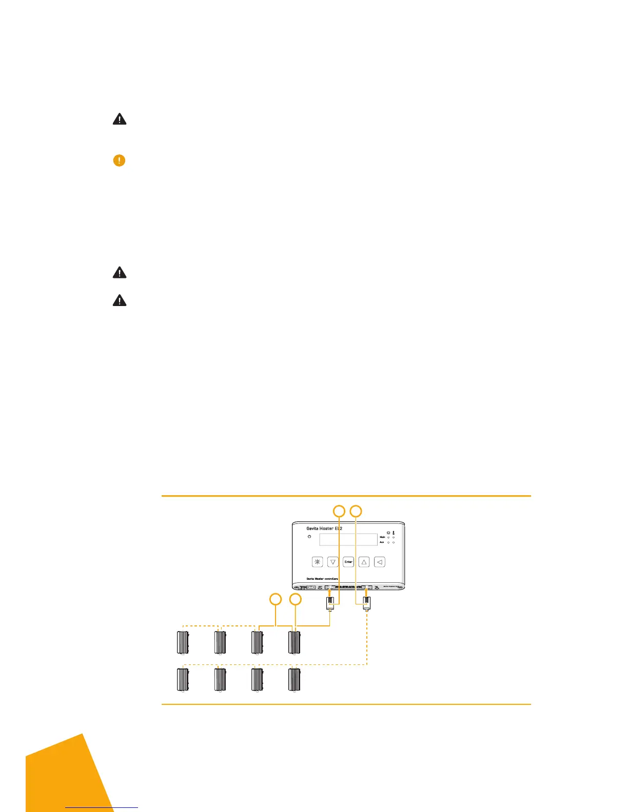
A group of up to 40 e-series ballasts can be connected to both the main RJ9
port and the auxiliary RJ9 port of the controller. Consult paragraph 4.3.1 to
connect the controller to remote ballasts. Consult paragraph 4.3.2 to connect
the controller to complete fixtures.
4.3.1. Connecting the controller to remote ballasts
Warning! When connecting the fixture to the controller it may ignite. Make
sure either fixture power is disconnected or the controller is switched off.
Warning! Ensure the remote ballasts are connected to their lamps and
reflectors.
•
Switch the rotary knob on all Gavita ballasts to “EXT” (external control)
•
Plug the RJ9 end of one of the controller cable(s) (6A) into the RJ9 main
port of the controller. If a two room setup is used or if more than 40
ballast have to be connected, plug a second ballast connection cable in
the RJ9 aux port (6B)
•
Plug the RJ14 end of the controller cable(s) into one of the two RJ14
ports of the first ballast (6C)
•
Interconnect the remote ballast to the next ballast in line using an
interconnect cable with RJ14 plugs (6D). Up to 40 ballasts may be daisy
chained this way.
Max 40 Ballast
Main Channel
Aux Channel
Max 40 Ballast
C
A B
D
6 Connecting the controller to remote ballasts
 Loading...