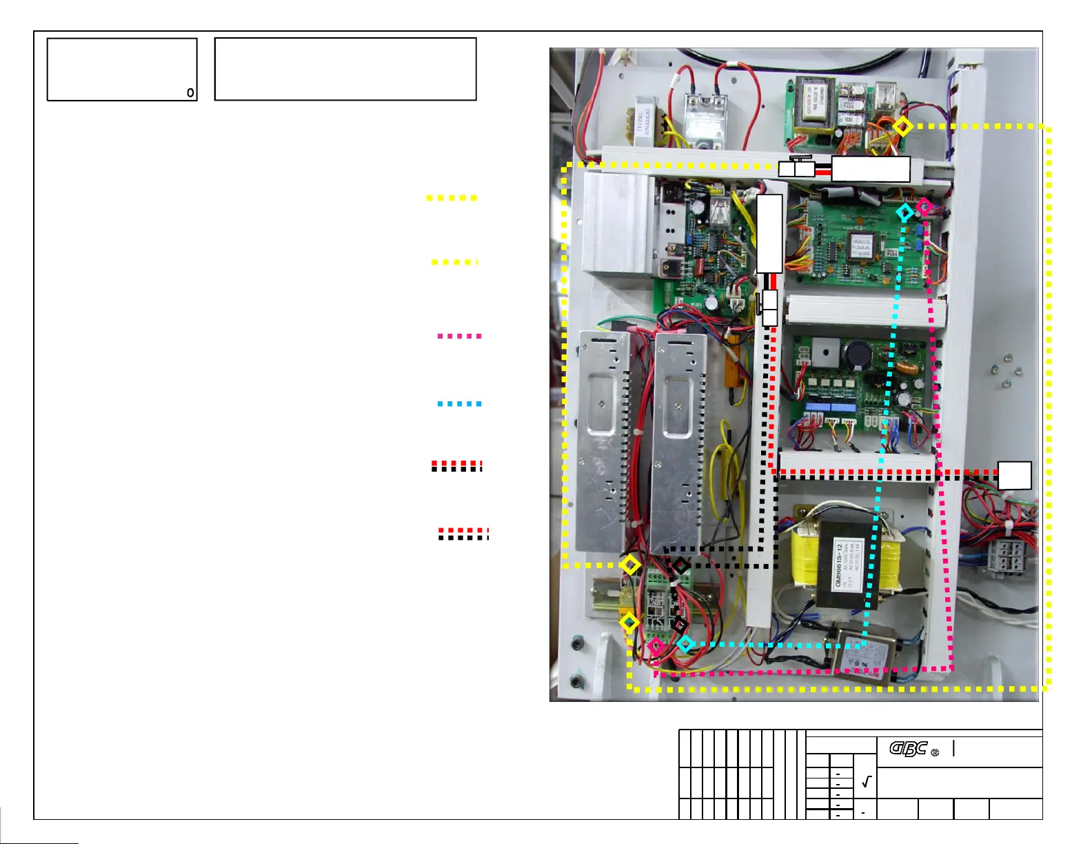
27 - The following steps will be connecting the wiring from the relays of the kit.
28 - From the top of Omron Relay 1, Connect the wires labeled “Main Motor”
to the plug for the Main Motor that is connected to the EMO Relay PCB. The
EMO Relay PCB “To Motor” socket will now be empty.
29 - From the bottom of the Omron Relay 1, connect the wires labeled “Motor
Relay Board” to the empty Motor socket of the EMO relay PCB.
30 - From the bottom of Phoenix Relay 1, connect the wires labeled “Fan” to
the empty fan socket (CN9) at the upper right corner of the main control PCB.
31 - From the bottom of Phoenix Relay 2, connect the wires labeled “Vac” to
the empty vac socket (CN4) at the upper right corner of the main control
PCB.
32 - From Phoenix Relay 2, connect the wires labeled “Vac Fuse” to the
Vacuum Fuse Holder.
33 - From Phoenix Relay 2, connect the wires labeled “Vacuum Fan ” to the
plug labeled “To Vacuum Fan” in previous step 2..
34 - Test the Laminator, confirm that all functions work then secure all wires.
Tie wrap or tuck in plastic wire channels as needed.
35 - Reinstall the electronics area metal cover box. It may be necessary to flex
the bottom open outward a bit.
36 - Reinstall machine side panel(s). Test all functions once again. Finished.
6175 E. Metro Dr. DeForest, WI 53532
This print is the property of GBC. The information thereon is remitted in confidence.
UNLESS OTHERWISE SPECIFIED
TOLERANCE
DIM. AS
SHOWN
TOL.
+ 1/64
+ .050
+ .020
+ .010
+ .005
X/X
X
XX
XXX
XXXX
ANGLES
+ 1D
FINISH
TO BE
125
TITLE :
DATE : DRAWN BY : DWG SCALE : DWG :
REVISION
CHECKED BY : Mike Taylor
Relays, 005-187 Kit Install
GBC Orca 64 TH
O64TH- KITP4
N/AMT02/19/07
Industrial & Print
Finising Group
MANUFACTURE OR FOR ANY OTHER PURPOSE WITHOUT WRITTEN
COPIED OR DISCLOSED IN WHOLE OR IN PART, OR USED FOR
FOR ENGINEERING INFORMATION ONLY AND SHALL NOT BE REPRODUCED,
GBC CLAIMS PROPRIETARY RIGHTS TO THE
MATERIAL DISCLOSED ON THIS DRAWING. IT IS ISSUED IN CONFIDENCE
PERMISSION FROM GBC.
PROPRIETARY
C
Note
Dotted Line = Wire Connection
Solid Line = Item Pointer
Vac
Fuse
To Vacuum
Fans
To Main
Motor