6175 E. Metro Dr. DeForest, WI 53532
This print is the property of GBC. The information thereon is remitted in confidence.
UNLESS OTHERWISE SPECIFIED
TOLERANCE
DIM. AS
SHOWN
TOL.
+ 1/64
+ .050
+ .020
+ .010
+ .005
X/X
X
XX
XXX
XXXX
ANGLES
+ 1D
FINISH
TO BE
125
TITLE :
DATE : DRAWN BY : DWG SCALE : DWG :
REVISION
CHECKED BY : Mike Taylor
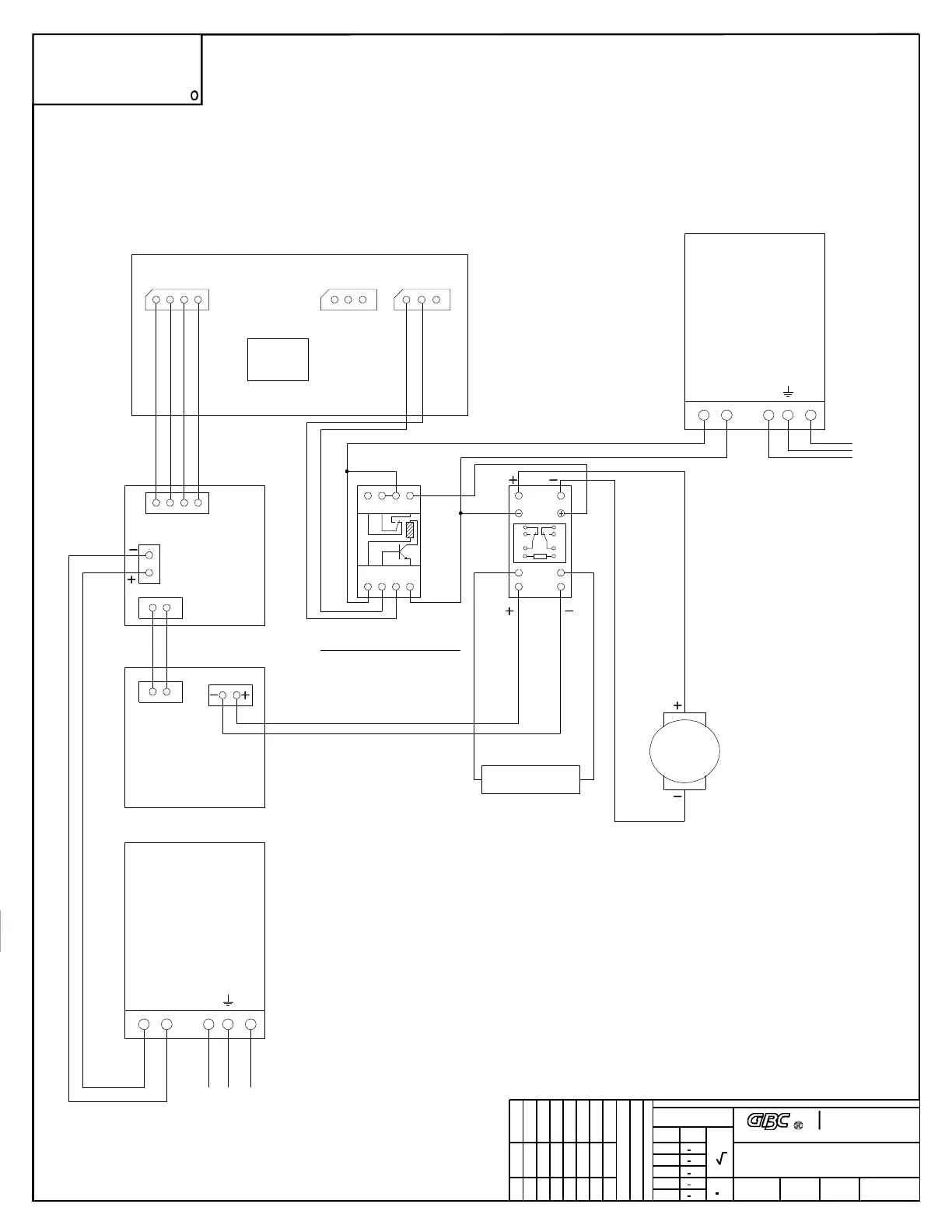
Motor Circuit Schematic 005-187 Kit
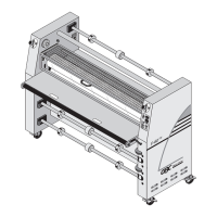
GBC Orca 64 TH
O64TH- KITP5
N/AJY02/19/07
Industrial & Print
Finising Group
MANUFACTURE OR FOR ANY OTHER PURPOSE WITHOUT WRITTEN
COPIED OR DISCLOSED IN WHOLE OR IN PART, OR USED FOR
FOR ENGINEERING INFORMATION ONLY AND SHALL NOT BE REPRODUCED,
GBC CLAIMS PROPRIETARY RIGHTS TO THE
MATERIAL DISCLOSED ON THIS DRAWING. IT IS ISSUED IN CONFIDENCE
PERMISSION FROM GBC.
PROPRIETARY
C
Main Board and Chip
2.6.4
MAIN_MOT VAC FAN
1 2 3 4 1 2 3
MAIN_MOT
1 - Ground
2 - PWM
3 - FWD/REV (High when Rev)
4 - Speed feedback.
VAC
1 - On/Off (High when On)
2 - Ground
3 - Not used
FAN
1 - Main motor On/Off (High when On,the
original PCB trace should be reconnected if
cut.)
2 - Ground
3 - Not used
Main motor
drive board
Relay board
Main
motor
A1 B A2 A2
12 11 11 14
Main
motor
Phoenix
Relay
9 12
13 14
1 4
5 8
1
5
9
4
8
12
13 14
Main
motor
Omron
Relay
V+ V - LN
24V DC
Power
supply
200W
Motor On Off
Phoenix On Off
Omron On Off
AC
input
Power
resistor
To_MOTOR
To_MOTOR
PCB
V+ V - LN
48V DC
Power
supply
200W
AC
input
ORCA TH 64 Kit Main Motor Drive
1 2 3
07/24/2006