GCI E84 Emulator Getting Started Manual Version 2.4a
GCI E84 Emulator Getting Started Manual
7
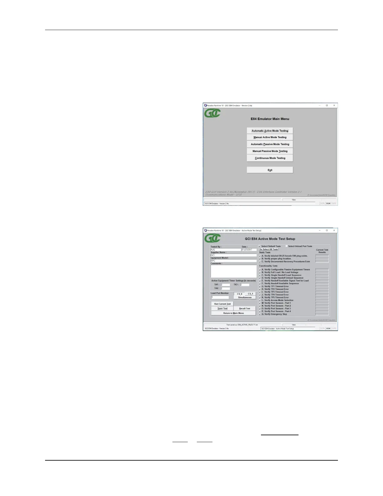
Main Menu
Automated Active Mode Test Setup Screen
Using the E84 Emulator GUI
The user interface is broken down into a series of menu, configuration, and test screens. The user
navigates through these screens by selecting option buttons (with mouse clicks, or keystrokes) provided
on each screen.
Main Menu
At startup, the E84 Emulator Main Menu is displayed.
At the lower left corner of the Main Menu, version
number information is displayed for both the GUI and
the E84 Emulator firmware. The communications
mode in use between the GUI and the E84 Emulator is
also shown.
Menu options are associated with a button on the Main
Menu. The desired menu option is selected by clicking
the button with the mouse, or using the keyboard to
activate the associated hot key. An underlined
character in the text of the button designates the
buttons hot key. Generally, the first unique character in
the buttons text is used for the hot key.
Automated Test Setup Screens
Test suite setup is performed in the Automated Active
Mode and Automated Passive Mode Test Setup
screens.
When running Active Mode tests, the E84 Emulator is
testing as the Active entity. Attach the female end of a
straight through, 25-pin, male-to-female cable
(provided) to the DB-25 connector labeled EMULATOR
IS ACTIVE EQUIPMENT on the E84 Emulator. Attach
the male end of the cable to the DB-25 E84 plug on the
passive equipment being tested.
When running Passive Mode tests, the E84 Emulator is
testing as the Passive entity. Attach the male end of a
straight through, 25-pin, male-to-female cable
(provided) to the DB-25 connector labeled EMULATOR
IS PASSIVE EQUIPMENT on the E84 Emulator. Attach the female end of the cable to the DB-25 E84
plug on the active equipment being tested.
Both test modes will also function through an attached optical transceiver. Attach an optical transceiver to
the female DB-25 connector labeled EMULATOR IS PASSIVE EQUIPMENT. Either Active or Passive
Mode tests will function through a properly attached optical transceiver.
The Automated Test Setup Screen is divided into two main sections. The left side of the screen provides
data fields for entering details about the equipment being tested.
For Active Mode Tests, the desired Active Mode timeouts can be entered in the three ACTIVE EQUIPMENT
TIMER SETTINGS box fields (TA1, TA2, TA3). The Load Port being tested is defined using the LOAD PORT
NUMBER buttons and field. For Simultaneous Handoff Mode testing, select the Simultaneous button. For
Single Handoff Mode testing, select either the CS_0 or CS_1 button.