GCI E84 Emulator Getting Started Manual Version 2.4a
GCI E84 Emulator Getting Started Manual
9
Continuous Mode Test Setup Screen
Continuous Handoff Test Setup Screen
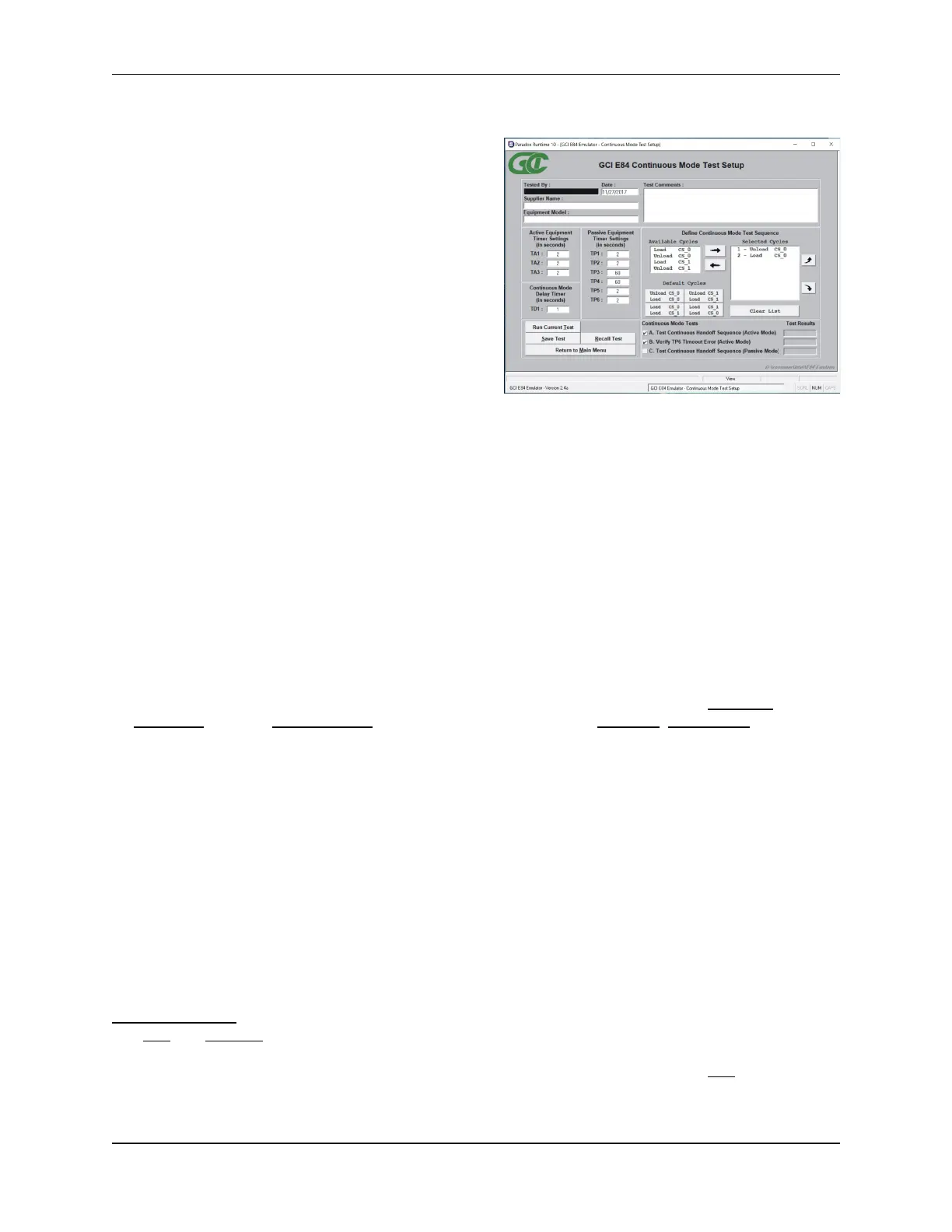
The Continuous Mode Test Setup Screen is used to
configure Continuous Handoff Mode tests. The
Continuous Mode Test Setup Screen is divided into
several sections.
Data entry fields allow the user to enter details about
the equipment being tested.
Active Mode timeouts are entered in the three ACTIVE
EQUIPMENT TIMER SETTINGS box fields (TA1, TA2, TA3).
Passive Mode timeouts are entered in the six PASSIVE
EQUIPMENT TIMER SETTINGS box fields (TP1, TP2, TP3,
TP4, TP5, TP6). Delay timer settings are entered in the
CONTINUOUS MODE DELAY TIMER box field (TD1).
A COMMENTS field is also provided to allow the user to
enter test specific comments.
All fields (with the exception of the COMMENTS field) must be entered before automated testing can begin.
The bottom right side of the screen lists check-off boxes to select pre-defined Continuous Mode Tests
provided by the E84 Emulator. The user simply checks off the desired tests. Next to each test definition
on the right side of the screen is a field that shows the current test results for each test. Initially, the fields
are empty since no tests have been run. Once each test is executed, the individual test results (Pass,
Fail, Untested) are displayed in these fields. For details on the available Continuous Mode tests, see the
Test Plans section towards the end of this manual.
Defining the Continuous Mode Test Sequence List
A DEFINE CONTINUOUS MODE TEST SEQUENCE box allows the user to define the specific order of handoff’s
to run during Continuous Handoff Mode testing. This box contains an AVAILABLE CYCLES list, a set of
DEFAULT CYCLE buttons, the current set of selected handoff’s (SELECTED CYCLES list), a Clear List button,
an Add Cycle button, a Remove Cycle button, and two sorting buttons (Move Up, Move Down) displayed
as arrows.
SELECTED CYCLES List
This field shows the list of currently selected handoff’s. When running test A (active mode), this list
defines the sequence of handoff’s requested by the E84 Emulator acting as the active equipment. When
running test C (passive mode), this list defines the sequence of handoff’s the E84 Emulator expects to
see when acting as the passive equipment. When running test B (TP6 Timeout Error), the first handoff in
the list is requested by the E84 Emulator, after which the TP6 timeout error is verified.
At least one handoff must be placed in this list before testing can begin.
AVAILABLE CYCLES List
There are four available handoff’s: Load CS_0, Unload CS_0, Load CS_1, Unload CS_1. Double-clicking
one of these cycles will add that cycle to the SELECTED CYCLES list.
Add / Remove Buttons
The Add and Remove buttons are located between the AVAILABLE CYCLES list and the SELECTED CYCLES
list, and take the shape of right and left arrows respectively. To Add a cycle, single click the desired cycle
in the AVAILABLE CYCLES list (the selected cycle will be highlighted in blue) and click the Add (right arrow)
button. The selected cycle will be added to the SELECTED CYCLES list.