EasyManua.ls Logo

GE Multilin 565 - User Manual

GE Multilin 565
198 pages
Print Icon
To Next Page IconTo Next Page
Loading...
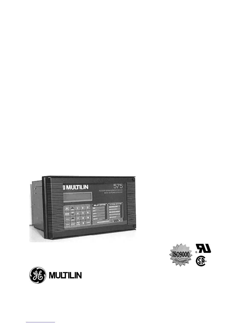
565/575
FEEDER MANAGEMENT RELAY
®
Instruction Manual
Software Rev: E2.73
Manual P/N: 1601-0017-E6
Copyright 1996 GE Multilin
CANADA USA
215 Anderson Avenue, Markham, Ontario, L6E 1B3 9746 Whithorn Dr., Houston, Texas, 77095
Tel: (905) 294-6222 Fax: (905) 294-8512 Tel: (713) 855-1000 Fax: (713) 859-1091

Table of Contents

Questions and Answers

  • K
    Karl BridgesAug 21, 2025
    How to troubleshoot phase overcurrent protection not energizing trip relay(s) in GE Multilin Other?
    • B
      Brianna CarrilloAug 22, 2025
      To troubleshoot phase overcurrent protection not energizing trip relay(s) on your GE Multilin Other, first check the phase CT rating, connections, and polarity. Then, verify that the correct protection curve, pickup level, and curve number have been entered in setpoints. If you've chosen a custom curve, use the Line Down key to check the time to trip for each breakpoint. Finally, perform a calibration mode relay test to verify the operation of the trip relay.
  • J
    Jonathan HansonSep 5, 2025
    How to fix ground fault instantaneous trips not operating on GE Multilin 565 Other?
    • R
      Richard PowellSep 5, 2025
      To address ground fault instantaneous trips not operating on your GE Multilin Other, check that the ground fault instantaneous trips are enabled in setpoints.
  • E
    Erica RobinsonSep 4, 2025
    Why phase overcurrent protection causes trip but no alarm in GE Multilin 565?
    • M
      Molly DudleySep 4, 2025
      To troubleshoot why the phase overcurrent protection causes a trip but no alarm on your GE Multilin Other: 1. Check that the phase overcurrent alarm is enabled in setpoints. 2. Verify the relay to which the alarm signal has been assigned. 3. Check that the alarm level setpoint is less than the trip level setpoint, and that the fault current is between these two values. 4. Check the phase overcurrent alarm time delay setpoint and ensure that the alarm condition is present for longer than this time. 5. Perform a calibration mode relay test to verify operation of the assigned relay(s).
  • S
    Sue HarveySep 2, 2025
    How to correct incorrect voltage readings displayed on GE Multilin 565 Other?
    • E
      Emily MartinSep 3, 2025
      To correct incorrect voltage readings displayed on your GE Multilin Other: 1. Check that the correct voltage is appearing at the 565 VT terminals. 2. Check that the correct voltage transformer sensing system, nominal secondary voltage, and feeder primary voltage have been entered in setpoints.
  • S
    Sarah SandovalSep 1, 2025
    How to display voltage readings on GE Multilin Other?
    • A
      alisonlopezSep 1, 2025
      If you are not seeing voltage readings displayed on your GE Multilin Other: 1. Verify that the voltage readings are selected for display by using the LINE DOWN key to view the messages in actual values page 6. 2. Verify that the VT wiring connections have been correctly made.
  • K
    Kenneth FloresAug 31, 2025
    How to correct incorrect phase current readings displayed on GE Multilin Other?
    • L
      Laura HillAug 31, 2025
      To resolve incorrect phase current readings displayed on your GE Multilin Other: 1. Measure the current flowing into the 565 CT terminals using a clamp-on ammeter. 2. Check that the correct phase CT primary rating has been entered and stored in setpoints.
  • A
    Andrew StevensAug 29, 2025
    What to do if GE Multilin Other display lights but power up message doesn't appear?
    • D
      Danny CarterAug 29, 2025
      If the display lights up but the power up message does not appear on your GE Multilin Other, verify that the control voltage is within the limits indicated on the serial number found on the side of the relay chassis.
  • E
    Eric McintyreAug 27, 2025
    How to display phase current readings on GE Multilin 565 Other?
    • M
      mullinsdavidAug 28, 2025
      To resolve the issue of no phase current readings displayed on your GE Multilin Other: 1. Verify that the current readings are selected for display by pressing the ACTUAL VALUES key and the LINE DOWN key to view the messages in actual values page 1. 2. Verify that the phase current wiring is correct. 3. Perform the phase current input function check.
  • L
    Lori JenkinsAug 26, 2025
    How to fix phase instantaneous trips not operating in GE Multilin Other?
    • D
      Daniel TaylorAug 27, 2025
      If phase instantaneous trips are not operating on your GE Multilin Other, check that the phase instantaneous trips are enabled in setpoints. Also, check the phase instantaneous trip level setpoint and verify that the current is exceeding this level.
  • R
    Roger FarmerAug 23, 2025
    How to fix GE Multilin 565 Other display that does not light up?
    • J
      jacobthompsonAug 23, 2025
      If the display of your GE Multilin Other does not light up, you should: 1. Check the control power voltage and connections at terminals 62 to 64. 2. Verify that the control voltage is within the limits indicated on the serial number label found on the side of the relay chassis. 3. Check the control power fuses. 4. Ensure that the relay is fully inserted into the drawout case.

Summary

SECTION 1: INTRODUCTION

Setpoint Programming

Details local setpoint programming via keypad and LCD, with step-by-step instructions.

SECTION 2: INSTALLATION

Programming Port

Explains the front panel RS232 port for connecting a computer for setpoints and data retrieval.

SECTION 3: PROTECTION APPLICATION INFORMATION

Overcurrent Protection

Explains continuous monitoring of phase/ground currents and initiation of alarms or trips.

SECTION 4: DISPLAY AND KEYBOARD

Actual Values Mode

Explains viewing monitored parameters using LINE UP/DOWN and PAGE keys.

Setpoints Mode

Details viewing and entering relay setpoints, including user levels.

SECTION 7: FEATURE INFORMATION

Event Recording Information

Explains the event recording feature, definitions, types, storage, and format.

SECTION 8: RELAY TESTING

Primary Injection Testing

Describes checking system operation by injecting current and providing potential source.

Secondary Injection Testing

Details single-phase injection testing applicable to the relay and its setpoints.

Phase Current Input Function Check

Verifies the relay reads phase current signals correctly from CTs using a test setup.

Phase Instantaneous Pickup and Trip Check

Guides on testing phase A instantaneous overcurrent pickup and trip functionality.

Phase Overcurrent Curve Verification

Explains how to verify the selected overcurrent curve shape and number against theoretical trip times.

Ground Current Input Function Check

Determines if the relay correctly reads ground current values using the test setup.

Ground Instantaneous Pickup and Trip Check

Details testing ground current conditions by injecting current and checking relay activation.

Ground Curve Verification

Guides on verifying the ground protection curve and its measured time against specifications.

Voltage Input Function Check

Checks if the relay correctly reads VT nominal secondary voltage and feeder primary volts.

Undervoltage Trip and Alarm Check

Details enabling and testing undervoltage trip and alarm functions by adjusting phase voltage.

Overvoltage Trip and Alarm Check

Explains enabling and testing overvoltage trip and alarm functions by increasing phase voltage.

Power Loss Check

Verifies that fault indication and setpoints remain unaffected after power interruption.

SECTION 9: TECHNICAL SPECIFICATIONS

Phase Overcurrent Protection

Specifies ranges and selections for timed and instantaneous overcurrent pickup and delay.

Ground Overcurrent Protection

Details ranges and selections for timed and instantaneous ground overcurrent pickup and delay.

Phase Current Inputs

Lists CT secondary/primary ratings, saturation, burden, and ratings.

Ground Current Input

Details CT secondary/primary ratings, saturation, burden, and ratings for ground current.

Voltage Inputs

Covers input configurations, burden, display accuracy, and RMS values for voltages.

Overvoltage Alarm and Trip

Specifies pickup and delay ranges for overvoltage alarms and trips.

Undervoltage Alarm and Trip

Details pickup and delay ranges for undervoltage alarms and trips.

APPENDIX B

Troubleshooting guide.

Lists common malfunctions with actions and references for diagnosis and resolution.

GE Multilin 565 Specifications

General IconGeneral
Frequency50/60 Hz
Current Inputs3
DisplayLCD
Communication ProtocolsModbus RTU, Modbus TCP/IP
WeightApprox. 2.5 kg
Protection FunctionsThermal Overload
MountingPanel Mount
CertificationsUL, IEC
Operating Temperature-20°C to +60°C

Related product manuals