FireShield Technical Reference Manual 2.1
Chapter 2
Installation
Installation checklist
Prepare the site: Make sure the installation location is
free from construction dust and debris and extreme
temperature ranges and humidity.
Unpack the equipment
Install the cabinet: See “Installing the cabinet” for cabinet
dimensions.
Remove the clear protective plastic from the front
panel display
Install optional components (FSRSI, FSDACT, etc.):
See module installation instructions in this chapter.
Set the panel jumpers: See Appendix C or the panel
label.
Review wire routing: See Appendix C or the panel label.
Connect the field wiring: See Appendix C or the panel
label. Meter for opens, grounds, and shorts before
connecting.
Connect AC power and ground: See Appendix C or the
panel label. Panel can not be started on batteries only.
WARNING: Make sure that the AC power circuit breaker
is off before connecting wires to the terminal block.
Connect batteries: See Appendix C or the panel label.
Program the panel: Refer to Chapter 3.
Test for proper operation
Installing the cabinet
Cabinets can be surfaced mounted or semi-flush mounted. See
the “Panel dimensions” figure and table for framing and
mounting dimensions.
To surface mount the cabinet:
1. Position the cabinet on the finished wall surface.
2. Fasten the cabinet to the wall surface where indicated.
To semi-flush mount the cabinet:
1. Frame the interior wall as required to support the full
weight of the cabinet and standby batteries.
2. Install (optional) semi-flush trim to cabinet.
3. Fasten the cabinet to the framing studs where indicated.
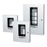
Panel dimensions
ModelD1 [1]D2D3D4D5 [1]
Three-
and five-
zone
16.5 in
(41.9
cm)
3.75 in
(9.5 cm)
9.13 in
(23.2
cm)
10.5 in
(26.67
cm)
14.23 in
(36.14
cm)
Ten-
zone
23.65 in
(60 cm)
3.75 in
(9.5 cm)
7.75 in
(19.7
cm)
21.27 in
(54.0
cm)
16.25 in
(41.27
cm)
[1] Add 1-1/2 in (3.81 cm) to D1 and D5 dimensions for trim kit.
D1
D2 D3
D4
D5
Surface mounting holes
Semi-flush mounting holes