Installation
2.2 FireShield Technical Reference Manual
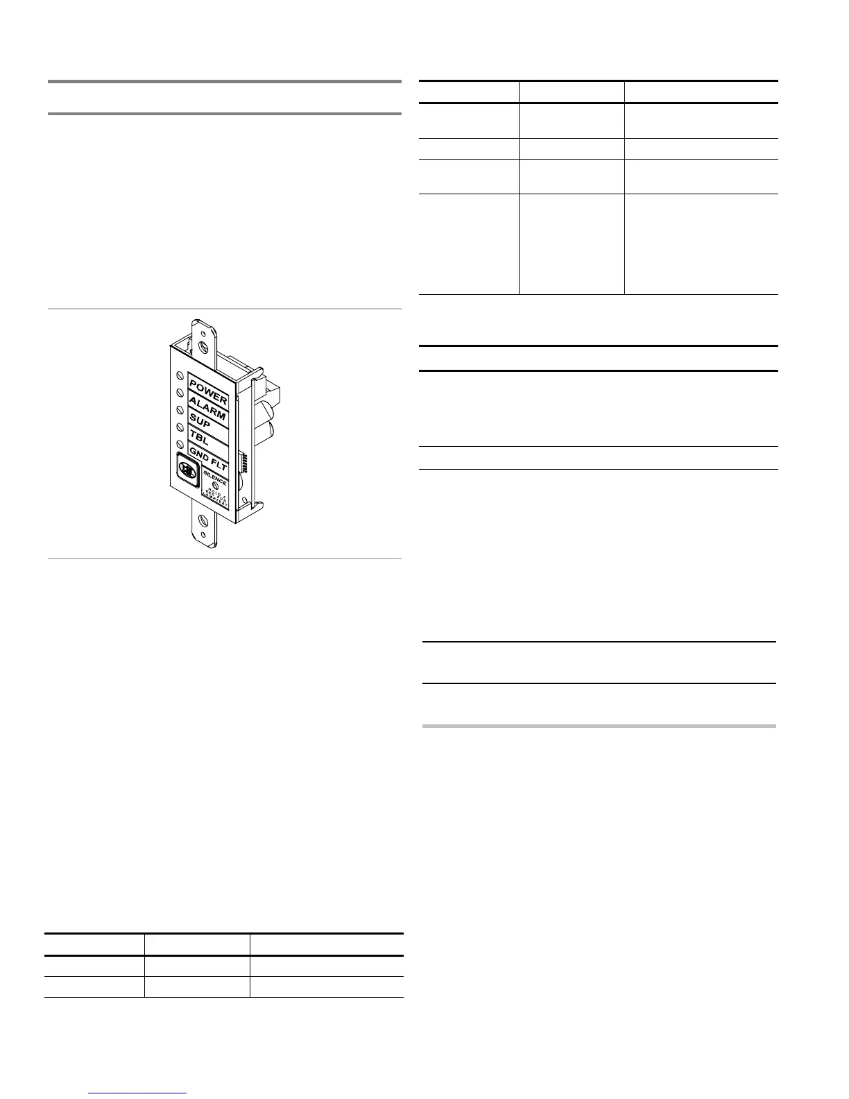
Installing the Remote System Indicator
The Remote System Indicator (FSRSI) is a supervised remote
annunciator that provides remote LED indication of power,
alarm, supervisory, trouble, and ground fault conditions. A
sounder gives audible indication during a trouble, alarm, or
supervisory condition. The sounder can be silenced with the
FSRSI Silence switch.
Note: You must run the Find Annunciators program option
after adding or removing a remote annunciator. The remote
annunciators will not operate properly until the panel detects
them. For more information see Chapter 3 “Programming.”
Specifications
Max. per system: 2
Voltage range
Minimum: 21 Vdc
Maximum: 25 Vdc
Current requirements
Standby: 12 mA
Alarm: 48 mA
Max. circuit capacitance: 0.03 µF
Max. circuit resistance: 13 ohms
Wire size
Minimum: 18 AWG (0.75 sq mm)
Maximum: 12 AWG (2.5 sq mm)
Compatible electric box: ANSI/NEMA OS1-1996 1-3 gang
electrical box
Operating environment
Temperature: 32 to 120 °F (0 to 49 °C)
Humidity: 93% RH, noncondensing
LEDs and buzzer
LED State Description
Power (green) On AC power present
Alarm (red) On Active alarm state
LED State Description
Supervisory
(yellow)
On Active supervisory device
Trouble (yellow) On System trouble
Ground fault
(yellow)
On System ground fault
Buzzer On
On (temporal)
On (slow pulse)
On (intermittent)
Off
System trouble
Alarm condition
Supervisory condition
AC fail
Normal or silenced
Jumper setup
Jumper Name Description
J2 Group
jumper
Allows two FSRSIs to be connected
to the same panel.
Install the jumper on only one of the
two FSRSIs.
Note: For jumper location, refer to the FSRSI wiring diagram.
Installation instructions
A single FSRSI can be mounted in a standard, single gang
electrical box (ANSI/NEMA OS1-1996) using the single gang
cover plate that is included. Up to three FSRZI-As with or
without an FSRSI can be mounted in an approved multiple
gang electrical box (ANSI/NEMA OS1-1996) with
appropriate two, three, or four gang cover plates (model
numbers FSAT-2, FSAT-3, or FSAT-4).
Caution: Make sure all power is disconnected from the panel
before installing. Observe static-sensitive handling practices.
To install the FSRSI:
1. Verify that all field wiring is free of opens, shorts, and
ground faults.
2. Connect wires to the FSRSI as shown (see wiring diagram).
3. Using the two plain machine screws provided, mount the
module to the electrical box.
Note: If you are using a surface mounting box, you must
install washers (provided) between the FSRSI and the
surface mounting box.
4. Using the white machine screws provided with the
faceplate, mount the faceplate to the module.
5. Connect the wires to the terminals in the control panel.
6. Program the FSRSI using the Find Annunciators program
option. Refer to Chapter 3 “Programming.”