Installation
FireShield Technical Reference Manual 2.3
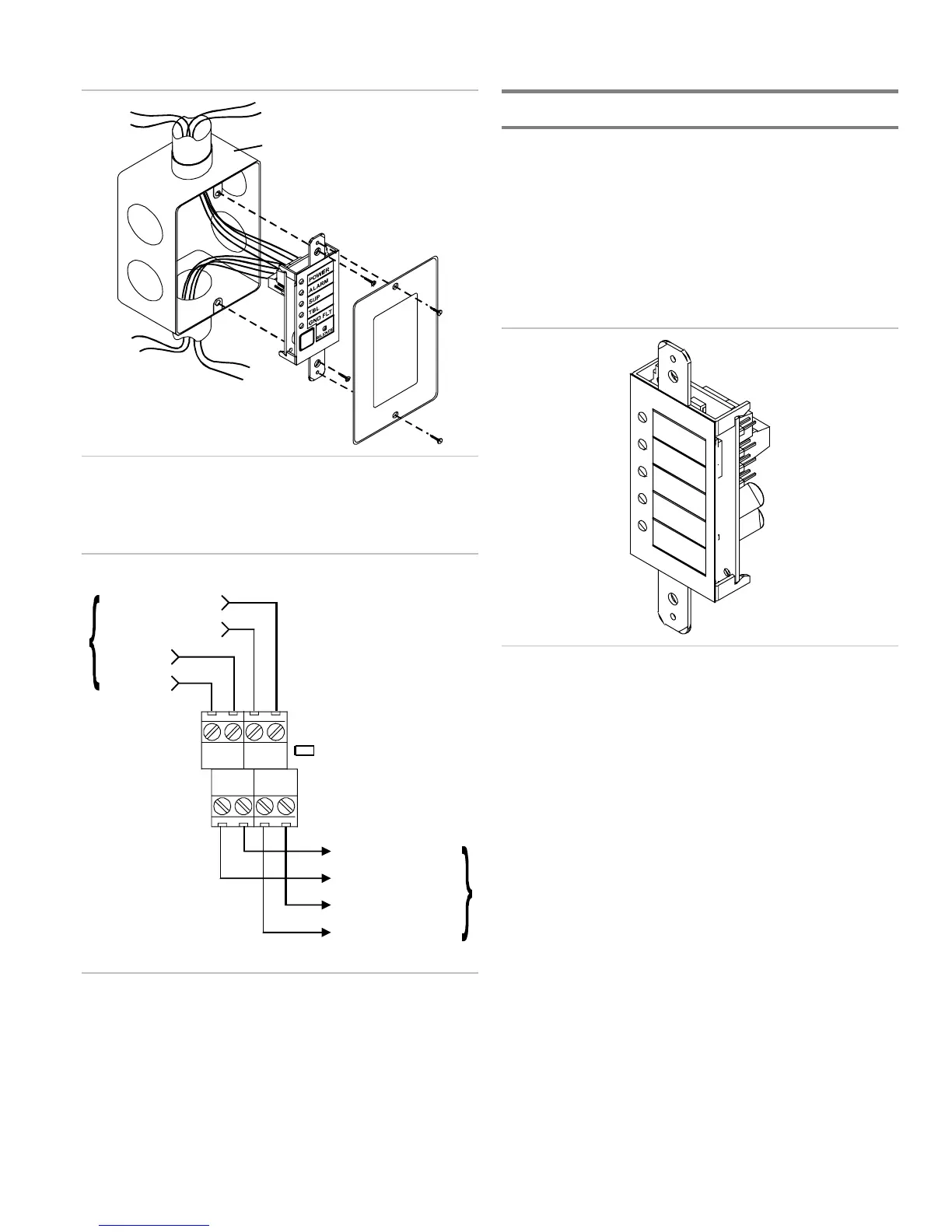
Compatible electrical box
Installing the FSRSI in an electrical box
Wiring diagram
Group
J2
24V IN
- +
C IN
+ -
C OUT
+ -
24V OUT
- +
24 V in +
24 V in -
Communication in -
Communication in +
Communication out +
Communication out -
From control panel
or previous device
To next device
24 V out +
24 V out -
Notes
1. All wiring is supervised and power limited.
2. 24 V out (aux power) must be programmed as non-
resettable.
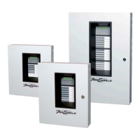
Installing the Remote Zone Indicator
The Remote Zone Indicator (FSRZI-A) is a supervised remote
annunciator that provides remote LED indication of IDCs in
alarm state. The FSRZI-A indicates conditions for five IDCs.
The IDC groups are set by jumpers to indicate zones 1–5 or
zones 6–10. Paper inserts are provided for labeling the LEDs.
Note: You must run the Find Annunciators program option
after adding or removing a remote annunciator. The remote
annunciators will not operate properly until the panel detects
them. For more information see Chapter 3 “Programming.”
Specifications
Max. per system
FS302 (three-zone): 2
FS502 (five-zone): 2
FS1004 (ten-zone): 4
Voltage range
Minimum: 21 Vdc
Maximum: 25 Vdc
Current requirements
Standby: 8 mA
Alarm: 35 mA
Max. circuit capacitance: 0.03 µF
Max. circuit resistance: 13 ohms
Wire size
Minimum: 18 AWG (0.75 sq mm)
Maximum: 12 AWG (2.5 sq mm)
Compatible electric box: ANSI/NEMA OS1-1996 1-3 gang
electrical box
Operating environment
Temperature: 32 to 120 °F (0 to 49 °C)
Humidity: 93% RH, noncondensing