Jumper settings and wiring diagrams
C.6 FireShield Technical Reference Manual
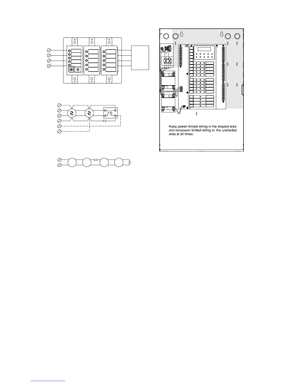
WATERFLOW / SUPERVISORY COMBINATION CIRCUIT
[4] [10]
(Only Class B allowed)
1.1 k
Ω
3.6 k
Ω
IDC1–
IDC1+
SS SSWFWF
REMOTE MODULE AND REMOTE RELAY WIRING
[6]
POWER
ALARM
SUP
TBL
GND FLT
SILENCE
LMPTST
C–
C+
24VDC+
24VDC–
REMOTE
RELAY
MODULE
(RRM)
TYPICAL FOUR-WIRE
SMOKE DETECTOR CIRCUIT
[2] [3] [7]
4.7 k
Ω
UL/ULC LISTED
EOL RELAY
(shown energized)
IDC1+
24VDC–
IDC2+
24VDC+
IDC1–
IDC2–
NOTES
1. All wiring is power-limited except for AC power and battery
wiring. All wiring is supervised unless otherwise noted.
[2] Dashed lines show Class A wiring
[3] Listed EOLRs must be installed as shown for proper
supervision. EOLRs are not required for Class A operation.
[4] For UL installations use EOLR P/N EOL3.6-1.1 which includes
one 1.1 k (P/N EOL1.1) and one 3.6 k (P/N EOL3.6)
resistor. For ULC installations use EOL-P1 and select the 1.1
k and 3.6 k resistors.
ΩΩ
ΩΩ
[5] Marking indicates output signal polarity when the circuit is
active. Polarity reverses when the circuit is not active. Wire
notification appliances accordingly. Notification appliance
polarity shown in active state.
[6] Requires continuous 24 Vdc from the AUX Power
terminals or a power-limited UL/ULC listed
compatible fire signaling power supply
[7] IDC circuits do not support alarm verification using
four-wire smokes. Requires resettable 24 Vdc from
AUX Power terminals.
[8] 5.0 A total with optional transformer (P/N XTR3A120
or XTR3A230
[9] Automatic and manually activated alarm initiating
devices can be installed on the same IDC circuit
regardless of circuit type except for combination
circuits (option 6, setting 5 and 6)
[10] Combination circuits consist of waterflow switches
(WF) and their associated valve tampers (SS)
[11] Relay circuits can only be connected to power-limited
sources
[12] Installation limits under jurisdiction of local authority
[13] Refer to the
(P/N 3100353) for the topic "Installing the FSDACT."
FireShield Technical Reference Manual