32 345 TRANSFORMER PROTECTION SYSTEM – QUICKSTART GUIDE
ELECTRICAL INSTALLATION CHAPTER 2: INSTALLATION
Breaker monitoring (Trip coil monitoring) is performed by a built-in voltage monitor on
Form A output relays: #1 Trip, and #2 Trip. The voltage monitor is connected across each of
the two Form A contacts, and the relay effectively detects healthy current through the
circuit. In order to do this, an external jumper must be connected between terminals A2
and A3 for #1 Trip coil monitoring, or/and B4, and B5 for #2 Trip coil monitoring.
As long as the current through the Voltage Monitor is above the threshold of the trickle
currents (see Technical Specification for Form A output relays), the circuit integrity for the
Trip coil is effectively normal. If the Trip coil circuit gets disconnected, or if in general a high
resistance is detected in the circuitry, a Trip alarm will be set and the “ALARM” and
“MAINTENANCE” LEDs will be on.
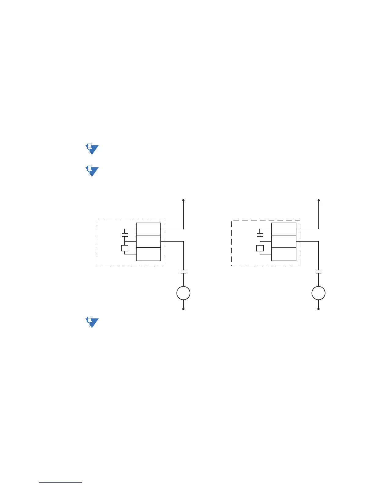
Example 1: The figures below show the two different connections of the breaker Trip coil to
the relay’s trip output #1 terminals (output #2 Trip coil monitoring) for both no voltage
monitoring and voltage monitoring of the trip circuit integrity.
NOTE:
To monitor the Trip coil circuit integrity, use the relay terminals A2 and B3 to connect the
Trip coil, and provide a jumper between terminals A2 (optional voltage) and A3.
NOTE:
To monitor the Trip coil circuit integrity, use the relay terminals B4 and A4 to connect the
Trip coil, and provide a jumper between terminals B4 (optional voltage) and B5.
Figure 2-20: Relay #1 Trip and Relay #2 Trip circuits with no voltage monitoring
NOTE:
All AUX contacts are shown when the breaker is open.
V
A2
B3
A3
Trip
Coil
DC +
DC -
Output Relay 1 (TRIP)
52a
contact
V
B4
A4
B5
DC +
Output Relay 2 (TRIP)
52a
contact
897785.cdr
Trip
Coil
DC -