CHAPTER 1: INTRODUCTION DESCRIPTION OF THE 345 TRANSFORMER PROTECTION SYSTEM
345 TRANSFORMER PROTECTION SYSTEM – QUICKSTART GUIDE 3
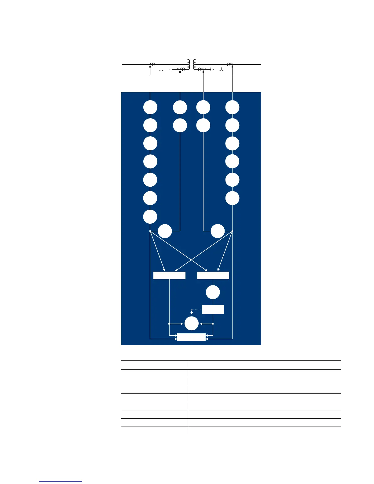
Figure 1-1: Single line diagram
Table 1-1: Protection Elements
ANSI Device Description
87T Percent Differential
50/87 Instantaneous Differential
87G Restricted Ground Fault
49 Thermal Model
50P Phase Instantaneous Overcurrent
50G Ground/Sensitive Ground Instantaneous Overcurrent
50N Neutral Instantaneous Overcurrent
50BF Breaker Failure
897743.CDR
345 RELAY
50G/
51G
50G/
51G
Metering
Calculate
Restraint Current
Calculate
Differential Currents
Calculate
Harmonics
2nd and 5th
BLOCK
50P50P 50G50G
51P
51P
51G
51G
50BF
50BF
51_2
51_2
50N
50N
51N
51N
87G
87G
87T
50/87
Winding 2
Winding 1
49P