8-2 SR3 SERIES PROTECTIVE RELAY PLATFORM – COMMUNICATIONS GUIDE
FUNCTION CODE 03H CHAPTER 8: MODBUS FUNCTIONS
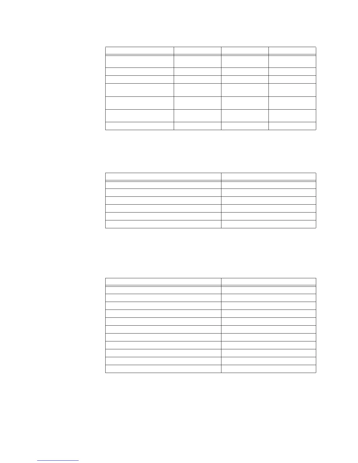
Query:
The query message specifies the starting register and quantity of registers to be read.
Registers are addressed starting at zero: registers 1 to 16 are addressed as 0 to 15.
Here is an example of a request to read registers 40172 to 40175 from slave device 254:
Response:
The register data in the response message are packed as two bytes per register, with the
binary contents right justified within each byte. For each register, the first byte contains
the high order bits and the second contains the low order bits.
The response is returned when the data is completely assembled.
The contents of register 40172 are shown as the two byte values of 00 FE hex, or254
decimal. The contents of registers 40173 to 40175 are 00 04, 00 00 and 00 00 hex, or 4, 0
and 0 decimal.
SLAVE RESPONSE BYTES EXAMPLE DESCRIPTION
SLAVE ADDRESS 1 11 message from slave
17
FUNCTION CODE 1 03 read registers
BYTE COUNT 1 06 3 registers = 6 bytes
DATA 1 (see definition above) 2 02 2B value in address
006B
DATA 2 (see definition above) 2 00 00 value in address
006C
DATA 3 (see definition above) 2 00 64 value in address
006D
CRC 2 54 83 CRC error code
Field Name Hex
Slave Address FE
Function 03
Starting Address Hi 00
Starting Address Lo AB
No. of Points Hi 00
No. of Points Lo 04
Field Name Hex
Slave Address FE
Function 03
Byte Count 08
Data Hi (Register 40172) 00
Data Lo (Register 40172) FE
Data Hi (Register 40173) 00
Data Lo (Register 40173) 04
Data Hi (Register 40174) 00
Data Lo (Register 40174) 00
Data Hi (Register 40175) 00
Data Lo (Register 40175) 00