2-12 SR3 SERIES PROTECTIVE RELAY PLATFORM – COMMUNICATIONS GUIDE
DNP PROTOCOL SETTINGS CHAPTER 2: RS485 INTERFACE
DNP serial EnerVista Setup
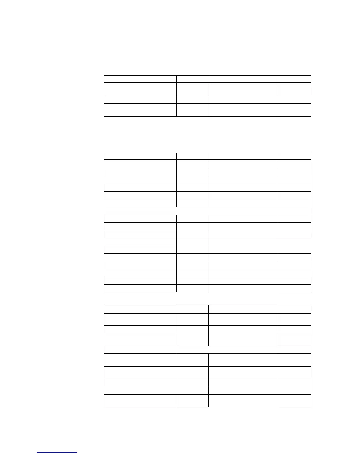
The following tables show the settings needed to configure all the DNP 3.0 implementation
parameters.
Table 2-1: RS-485
In order to activate DNP 3.0 at the RS485 rear port, the setting "Rear 485 Protocol" must be
set to DNP 3.0. Once the setting has been changed, the relay must be switched off, then
switched on.
Table 2-2: DNP protocol
Table 2-3: DNP point list
SETTINGS PARAMETER RANGE FORMAT
RS485 Baud Rate 115200 9600, 19200, 38400, 57600,
115200
F101
RS485 Comm Parity None None, Odd, Even F102
Rear 485 Protocol DNP 3.0 Modbus, IEC60870-5-103, DNP
3.0
F97
SETTINGS PARAMETER RANGE FORMAT
DNP Unsol Resp Function Disabled Disabled ; Enabled F126
DNP Unsol Resp Timeout 5 s 0 to 60 s F1
DNP Unsol Resp Max Retries 10 1 to 255 F1
DNP Unsol Resp Dest Addr 1 0 to 65519 F1
DNP Time Sync IIN Period 1440 min 1 to 10080 min F1
DNP Message Fragment Size 240 30 to 2048 F1
DNP Object 1 Default Variation 2 1 ; 2 F1
DNP Object 2 Default Variation 2 1 ; 2 F1
DNP Object 20 Default Variation 1 1 ; 2 , 5 ; 6 F78
DNP Object 21 Default Variation 1 1 ; 2 ; 9 ; 10 F79
DNP Object 22 Default Variation 1 1 ; 2 , 5 ; 6 F80
DNP Object 23 Default Variation 1 1 ; 2 , 5 ; 6 F81
DNP Object 30 Default Variation 1 1 ; 2 ;3 ; 4 F82
DNP Object 32 Default Variation 1 1 ; 2 ;3 ; 4 F83
DNP TCP Connection Timeout 120 s 10 to 300 s F1
Fault Report Mapping in DNP/104 Disabled Disabled, Enabled F126
SETTINGS PARAMETER RANGE FORMAT
Binary Input Point 0 Entry Select entry
from a list
Operands F134B
Binary Input Point 63 Entry Select entry
from a list
Operands F134B
Analog Input Point 0 Entry Select entry
from a list
Analog parameters F88
Analog Input Point 0 Scale Factor 1 0.001 ; 0.01 ; 0.1 ; 1 ; 10 ; 100 ;
1000 ; 10000 ; 100000
F85
Analog Input Point 0 Deadband 30000 0 to 100000000 F9
Analog Input Point 31 Entry Select entry
from a list
Analog parameters F88