3-18 SR3 SERIES PROTECTIVE RELAY PLATFORM – COMMUNICATIONS GUIDE
DNP ETHERNET PROTOCOL SETTINGS CHAPTER 3: ETHERNET INTERFACE
NOTE:
The setting DNP Unsolicited Response Timeout affects DNP TCP clients only; not serial
and UDP clients. Possible values that can be selected for this setting lie between 0 and 60
seconds.
In addition to this selected timeout, up to an additional 10 seconds is required to send
the response packet.
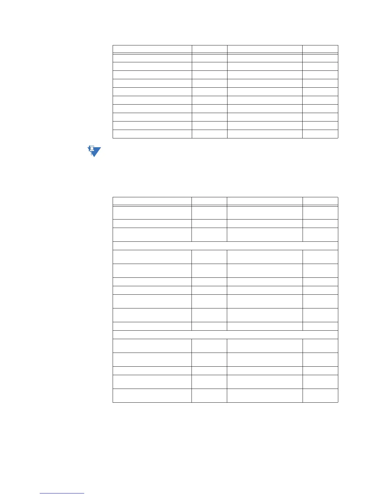
Table 3-2: DNP point list
• The DNP Time Sync IIN Period setting determines how often the Need Time Internal
Indication (IIN) bit is set by the 3 Series relay. Changing this time allows the 3 Series
relay
to indicate that a time synchroniztion command is necessary more or less often
DNP Object 1 Default Variation 2 1 ; 2 F1
DNP Object 2 Default Variation 2 1 ; 2 F1
DNP Object 20 Default Variation 1 1 ; 2 , 5 ; 6 F78
DNP Object 21 Default Variation 1 1 ; 2 ; 9 ; 10 F79
DNP Object 22 Default Variation 1 1 ; 2 , 5 ; 6 F80
DNP Object 23 Default Variation 1 1 ; 2 , 5 ; 6 F81
DNP Object 30 Default Variation 1 1 ; 2 ;3 ; 4 F82
DNP Object 32 Default Variation 1 1 ; 2 ;3 ; 4 F83
DNP TCP Connection Timeout 120 s 10 to 300 s F1
Fault Report Mapping in DNP/104 Disabled Disabled, Enabled F126
SETTINGS PARAMETER RANGE FORMAT
SETTINGS PARAMETER RANGE FORMAT
Binary Input Point 0 Entry Select entry
from a list
Operands FC134B
Binary Input Point 63 Entry Select entry
from a list
Operands FC134B
Analog Input Point 0 Entry Select entry
from a list
Analog parameters F88
Analog Input Point 0 Scale Factor 1 0.001 ; 0.01 ; 0.1 ; 1 ; 10 ; 100 ;
1000 ; 10000 ; 100000
F85
Analog Input Point 0 Deadband 30000 0 to 100000000 F9
Analog Input Point 31 Entry Select entry
from a list
Analog parameters F88
Analog Input Point 31 Scale Factor 1 0.001 ; 0.01 ; 0.1 ; 1 ; 10 ; 100 ;
1000 ; 10000 ; 100000
F85
Analog Input Point 31 Deadband 30000 0 to 100000000 F9
Binary Output Point 0 ON Select entry
from a list
Virtual Input 1 to 32 and Force
Coils
F86
Binary Output Point 0 OFF Select entry
from a list
Virtual Input 1 to 32 and Force
Coils
F86
Binary Output Point 15 ON Select entry
from a list
Virtual Input 1 to 32 and Force
Coils
F86
Binary Output Point 15 OFF Select entry
from a list
Virtual Input 1 to 32 and Force
Coils
F86