4-12 SR3 SERIES PROTECTIVE RELAY PLATFORM – COMMUNICATIONS GUIDE
GOOSE CONFIGURATION VIA THE 3 SERIES MENUS CHAPTER 4: 3 SERIES IEC61850 GOOSE
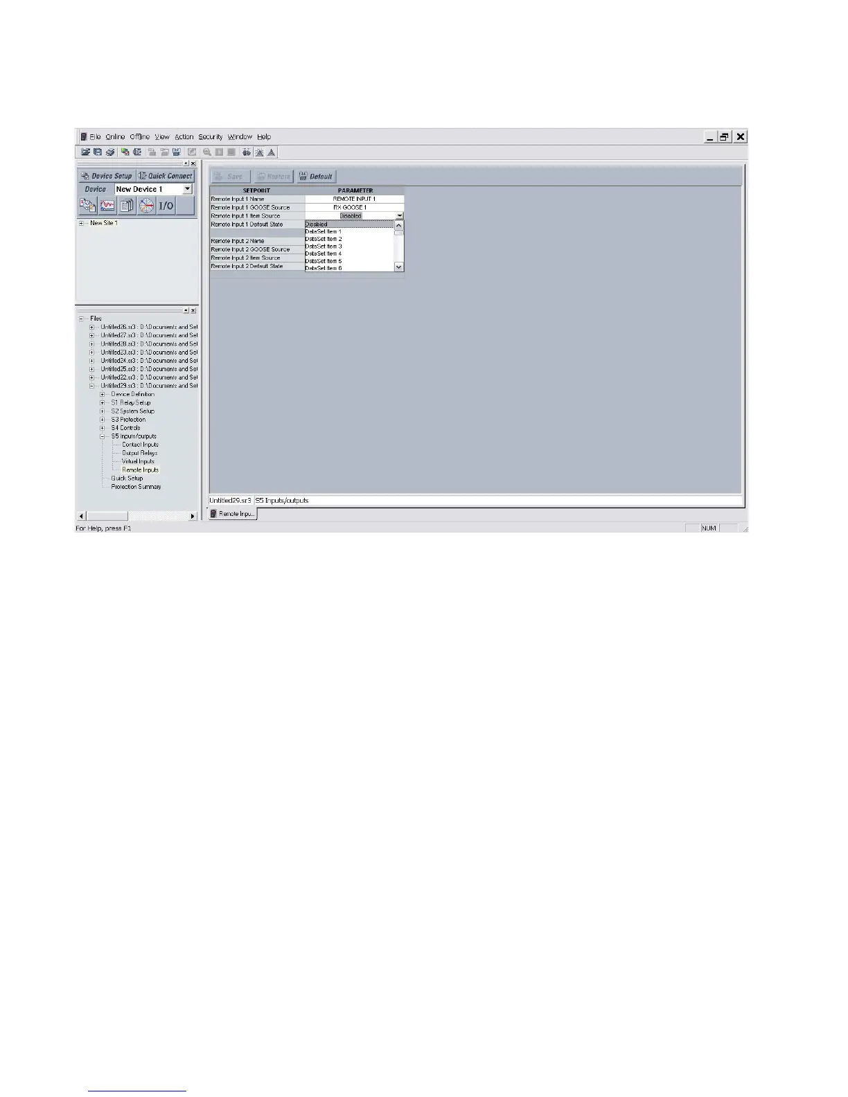
Figure 4-7: EnerVista 3 Series Setup GOOSE Remote Inputs - 2 of 2
The following format indicates the source of the GOOSE message:
The string name of each remote input is maintained in a set of MODBUS registers, where
each string name consumes up to 7 MODBUS registers.
Each GOOSE remote input can be mapped to one of the following functions:
• protection element block (all protection elements that have a single or multiple block
setting)
• user assignable LED
•digital output
• group setting change (350 and 345 only)
The 3 Series relay records changes in GOOSE remote inputs in the Event Log.
The time recorded in a GOOSE remote input’s event log entry, is the time at which the
change in the input’s state is detected.
The 3 Series relay invokes a logic (block / control) function when its corresponding GOOSE
remote input is asserted.
In the 3 Series relay there are many different settings where it is possible to select between
a Contact Input (1 to 10 ), a Virtual Input (1 to 32 ) or a Logic Element (1 to 16). In all of these
settings it is also possible to select Remote Input (1-32 ) if the GOOSE feature is enabled on
the relay.