Modifications reserved Page 10/79
OPM_SGS_USM_M40_M50_2US_V010.doc User Manual SG Series 400 & 500 UL S2
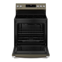
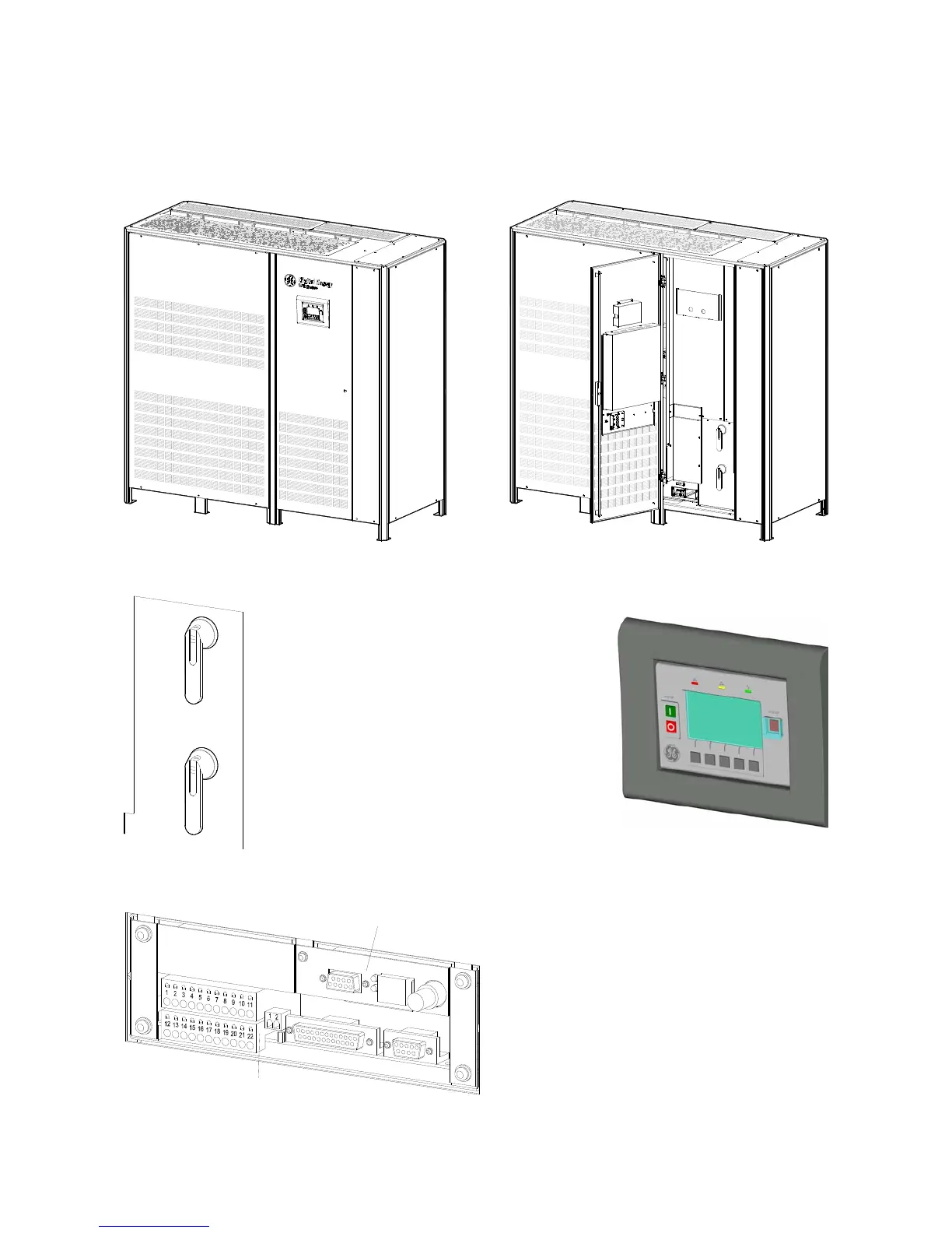
2 LAYOUT
2.1 LAYOUT SG Series 400 & 500
S
G
S
_
4
0
0
-
5
0
0
_
S
2
_
U
P
S
_
G
E
_
0
2
Fig. 2.1-1 SG Series 400 & 500 general view
Q1
0
O
F
F
I ON
Q2
0
O
F
F
I ON
S
G
S
U
_
4
0
0
-
5
0
0
_
S
2
_
U
P
S
_
0
3
11
22
10
21
2
1
18
12
13
16
1415
17
7
1
2
34
6
5
1920
8
9
4
3
2
1
15
14
1312
9
8
20
19
56
7
17
16
18
21
10
22
11
Fig. 2.1-2 SG Series 400 & 500 general view with open doors
SGS_400-500_S2_Switches Q1-Q2_01
Q1
0
O
F
F
I ON
Q2
0
O
F
F
I ON
Fig. 2.1-3 Manual operated switches
Fig. 2.1-4 Control panel
P4
Customer Interface Board
Q1
UPS output switch
Q2
Manual Bypass switch (option)
SNMP
3-ph SNMP/WEB plug-in adapter (option)
XA
Terminals for 24Vdc
Auxiliary Power Supply connection
S
G
S
_
4
0
0
-
5
0
0
_
C
u
s
t
o
m
e
r
in
t
e
r
f
a
c
e
_
0
3
P4
SNMP
Fig. 2.1-5 Connectivity Rack
XB
Terminals for EPO (Emergency Power
Off) connection