• 2 Insert the flat cable on J2 connector of the VH Prog. Board.
Fig. 2
• 3 Connect USB and the flat cable to the E8a Programmer.
Fig. 3
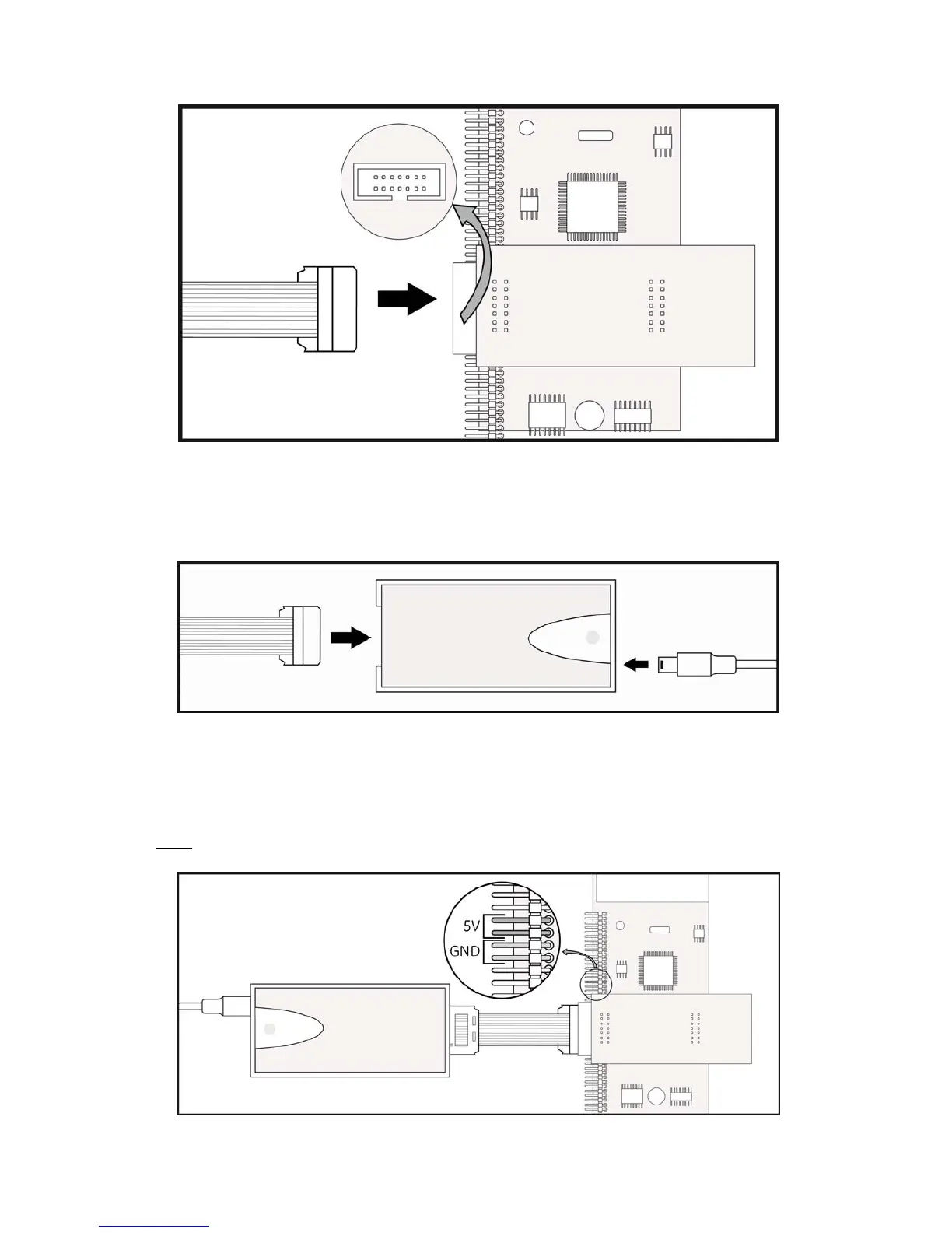
• 4 Top view of the final cabling for the firmware update with the VH Programming Board for
Digital Energy™ VH Series.
NOTE
: Pins 13 and 14 are 5V plug-in, and pins 15 and 16 are GND plug-in.
Fig. 4
Modifications reserved 10 ISG_VHS_FRM_UPD_XGB_V010.doc
 Loading...