3 - 8 750/760 FEEDER MANAGEMENT RELAY – COMMUNICATIONS GUIDE
CLOCK SYNCHRONIZATION OF MULTIPLE RELAYS CHAPTER 3: MODBUS FUNCTIONS
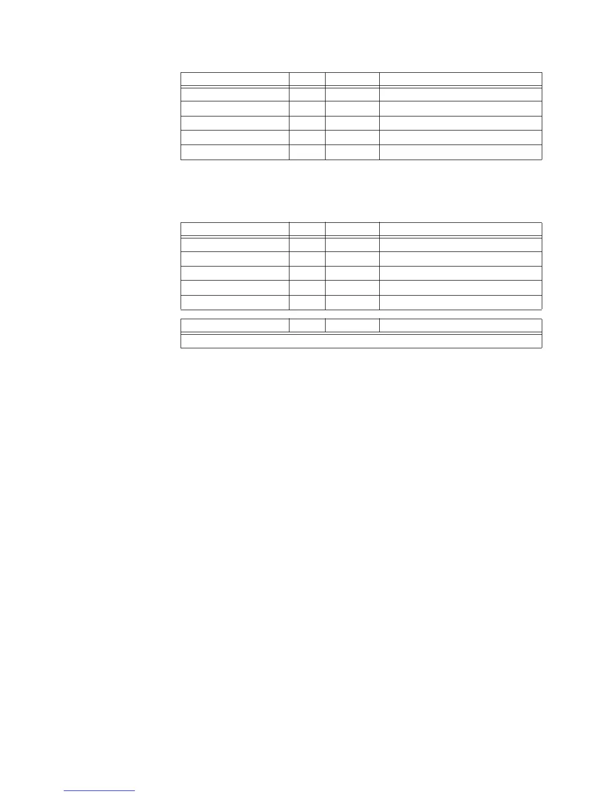
The following table shows the format of the master and slave packets for a master device
sending the Store Time operation code to all slave devices on the communications link as
required by step three of the procedure.
Slave Response Bytes Example Description
Slave Address 1 11 message from slave 11
Function Code 1 10 store multiple setpoints
Data Starting Address 2 10 06 data starting at 1006h
Number of Bytes 2 00 08 4 setpoints = 8 bytes total
CRC (low, high) 2 27 9B computed CRC error code
Master Transmission Bytes Example Description
Slave Address 1 11 message for slave 11
Function Code 1 05 execute operation
Operation Code 2 00 04 set time
Code Value 2 FF 00 perform operation
CRC (Low, High) 2 CC 2A computed CRC error code
Slave Response Bytes Example Description
No response from slave.

 Loading...


