CHAPTER 5: DNP COMMUNICATIONS DNP IMPLEMENTATION
750/760 FEEDER MANAGEMENT RELAY – COMMUNICATIONS GUIDE 5 - 3
Note 1: The data link layer confirmation mode, confirmation time-out, and number of
retries are all configurable. Refer to the DNP Configuration section in Chapter 5 of
the instruction manual for more details.
DNP Implementation
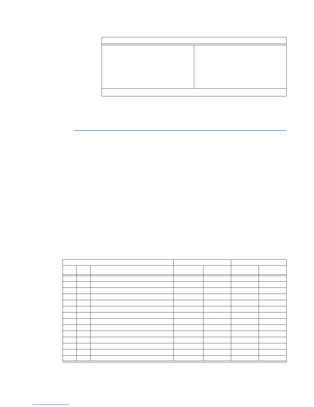
The table below gives a list of all objects recognized and returned by the relay. Additional
information is provided on the following pages including a list of the default variations
returned for each object and lists of defined point numbers for each object.
Implementation Table Notes:
1. For this object, the quantity specified in the request must be exactly 1 as there is only
one instance of this object defined in the relay.
2. All static input data known to the relay is returned in response to a request for Class 0.
This includes all objects of type 1 (Binary Input), type 10 (Binary Output) and type 30
(Analog Input).
3. The point tables for Binary Input and Analog Input objects contain a field which
defines to which event class the corresponding static data has been assigned.
4. For this object, the qualifier code must specify an index of 7 only.
Default Counter Object/Variation:
No Counters Reported
Configurable
Default Object / Default Variation
Point-by-point list attached
Counters Roll Over at:
No Counters Reported
Configurable
16 Bits
32 Bits
Other Value
Point-by-point list attached
Sends Multi-Fragment Responses: Yes No
DNP 3.0: DEVICE PROFILE DOCUMENT (Continued)
Table 1: DNP Implementation Table
Object Request Response
Obj Var Description Func Codes Qual Codes
(Hex)
Func Codes Qual Codes
(Hex)
1 0 Binary Input - All Variations 1 06
1 1 Binary Input 1 00, 01, 06 129 00, 01
1 2 Binary Input With Status (Note 6) 1 00, 01, 06 129 00, 01
2 0 Binary Input Change - All Variations 1 06, 07, 08
2 1 Binary Input Change Without Time 1 06, 07, 08 129 17, 28
2 2 Binary Input Change With Time 1 06, 07, 08 129 17, 28
10 0 Binary Output - All Variations 1 06
10 2 Binary Output Status 1 00, 01, 06 129 00, 01
12 1 Control Relay Output Block 3, 4, 5, 6 17, 28 129 17, 28
30 0 Analog Input - All Variations 1 06
30 1 32-Bit Analog Input With Flag 1 00, 01, 06 129 00, 01
30 2 16-Bit Analog Input With Flag 1 00, 01, 06 129 00, 01
30 3 32-Bit Analog Input Without Flag 1 00, 01, 06 129 00, 01
30 4 16-Bit Analog Input Without Flag 1 00, 01, 06 129 00, 01
1, 2, 3, 4, 5, 6: see the IMPLEMENATION TABLE NOTES above.

 Loading...


