Installation Instructions
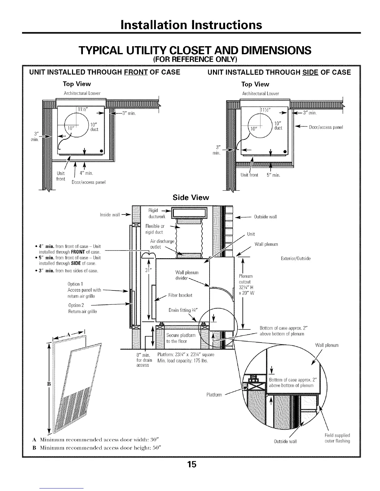
TYPICAL UTILITY CLOSET AND DIMENSIONS
(FOR REFERENCE ONLY)
UNIT INSTALLED THROUGH FRONT OF CASE UNIT INSTALLED THROUGH SIDE OF CASE
Top View Top View
ArcbitecturalLouver ArchitecturalLouver
111/Z'
4" ffdn.
Door/access pauel
Insidewall
• 4" min. fromfront of case Unit
installed throughFRONTof case.
• 5" min. fromfront of case Unit
installed throughSIDEof case.
• 3" min. fromtwo sides ofcase.
Option1
Accesspanelwith
returnairgrille
Option2
Returnair grille
3 _ _
rain.
Side View
Rigid --_
ductwork
Flexibleor _ /
rigid duct / /
Air discbarge_
_1" Wall plenum
a divider-.........__-. l
I F FHterbracket
; 7--
pto t e f oor .....
8" rain. Platform:231/4"x 231/4" square
for drain Min. loadcapacity: 175Ibs.
access
t1:t
,_-- 3" rain.
D00r/accesspanel
Uuitfront 5" min.
Outsidewall
Unit
Wall plenum
/
l Exterior/Outside
Plenum
cutout
321/4"H
x20"W
Bottomof case approx.2"
/ abovebottom of plenum
Wall plenum
Platform
A _([il/ir///lrll F(!COl//]//Clld(!d _tcc(_ss dooF _ldth" o0"
B Minimum re(ommended a((ess door heigl]u 50"
Fieldsupplied
Outsidewall outerflashiug
15
 Loading...