2-88 UR FAMILY – COMMUNICATIONS GUIDE
MEMORY MAP CHAPTER 2: MODBUS COMMUNICATION
2
" 65DE Power Swing Detect Middle Left Blinder 0.1 to 500 ohms 0.01 F001 10000
" 65DF Power Swing Detect Inner Right Blinder 0.1 to 500 ohms 0.01 F001 10000
" 65E0 Power Swing Detect Inner Left Blinder 0.1 to 500 ohms 0.01 F001 10000
" 65E1 Power Swing I2 Supervision Enable 0 to 4294967295 --- 1 F300 0
" 65E3 Power Swing I2 Supervision 0.05 to 30 pu 0.001 F001 200
Bus Configuration (Read/Write Setting) (6 Modules)
B90 65EE Bus Zone 1 Status (24 items) 0 to 4294967295 --- 1 F300 0
Motor Setup (Read/Write Setting)
M60 6600 Thermal Model Motor FLA 0.05 to 1 pu 0.001 F001 1000
" 6601 Thermal Model Motor Service (Overload)
Factor
1 to 1.5 --- 0.01 F001 100
" 6602 Thermal Model Line Source 0 to 5 --- 1 F167 0 (SRC 1)
" 6603 Thermal Model Motor Offline 0 to 4294967295 --- 1 F300 0
" 6605 Thermal Model RTD 1 0 to 48 --- 1 F151 0 (NONE)
" 6606 Thermal Model RTD 2 0 to 48 --- 1 F151 0 (NONE)
" 6607 Thermal Model RTD 3 0 to 48 --- 1 F151 0 (NONE)
" 6608 Thermal Model RTD 4 0 to 48 --- 1 F151 0 (NONE)
" 6609 Thermal Model RTD 5 0 to 48 --- 1 F151 0 (NONE)
" 660A Thermal Model RTD 6 0 to 48 --- 1 F151 0 (NONE)
" 660B Motor Emergency Restart 0 to 4294967295 --- 1 F300 0
" 660D Motor Nameplate Voltage 100 to 50000 V 1 F001 600
" 660E Speed 2 Motor Protection 0 to 1 --- 1 F102 0 (Disabled)
" 660F Speed 2 Motor Switch 0 to 4294967295 --- 1 F300 0
" 6611 Speed 2 Switch 2-1 Delay 0 to 600 s 0.01 F001 500
" 6612 Speed 2 Motor Source 0 to 5 --- 1 F167 0 (SRC 1)
" 6613 Speed 2 Motor FLA 0.05 to 1 pu 0.001 F001 1000
Bus Configuration (Read/Write Setting) (6 Modules)
B90 661E ...Repeated for Bus Zone 2
Thermal Model Actual Values (Read Only)
M60 6630 Thermal Model Motor Status 0 to 3 --- 1 F098 1 (Starting)
" 6631 Thermal Model Capacity Used 0 to 100 % 1 F001 0
" 6633 Trip Time On Overload 0 to 10000 --- 1 F001 0
" 6634 Thermal Model Lockout Time 0 to 65000 min 1 F001 0
Thermal Model Actuals (Read Only)
M60 6638 Thermal Model Load 0 to 40 x FLA 0.01 F001 0
" 663A Thermal Model Motor Unbalance 0 to 100 % 1 F001 0
" 663B Thermal Model Biased Motor Load 0 to 40 x FLA 0.01 F001 0
" 663C Start/Hour Lockout Time 0 to 65000 min 1 F001 0
" 663D Time-Between-Starts Lockout Time 0 to 65000 min 1 F001 0
" 663E Restart Delay Lockout Time 0 to 65000 s 1 F001 0
" 663F Total Motor Lockout Time 0 to 65000 min 1 F001 0
Field Ground Actual Values (Read Only)
G60 6640 Field Ground Resistance 0 to 20000 kOhm 0.001 F003 20000000
" 6642 Field Ground Current 0 to 655.35 mA 0.01 F001 0
" 6643 Field Ground Injected Voltage -32.767 to 32.767 V 0.001 F002 0
" 6644 Field Ground Fault Location -30000 to 30000 % 1 F002 -10
" 6645 Field Ground Field Voltage -3276.8 to 3276.7 V 0.1 F002 0
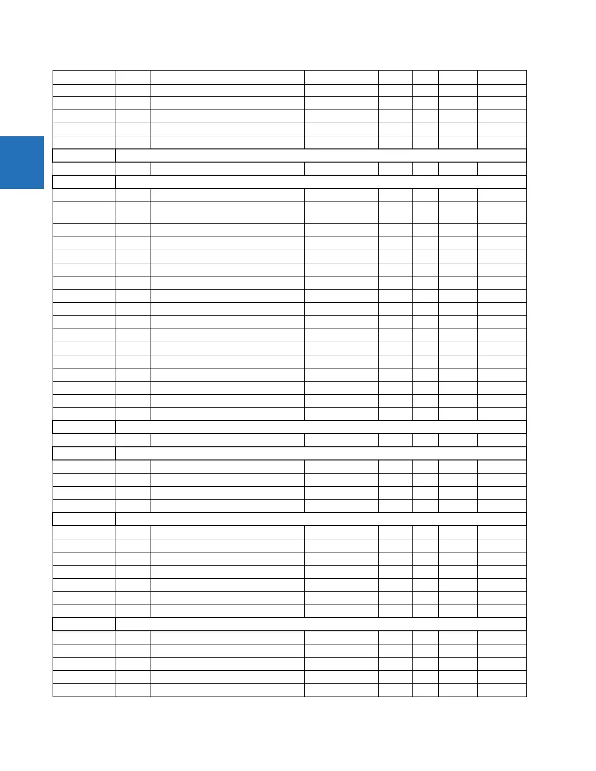
Products Address Register name Range Units Step Format Default

 Loading...


