2-38 UR FAMILY – COMMUNICATIONS GUIDE
MEMORY MAP CHAPTER 2: MODBUS COMMUNICATION
2
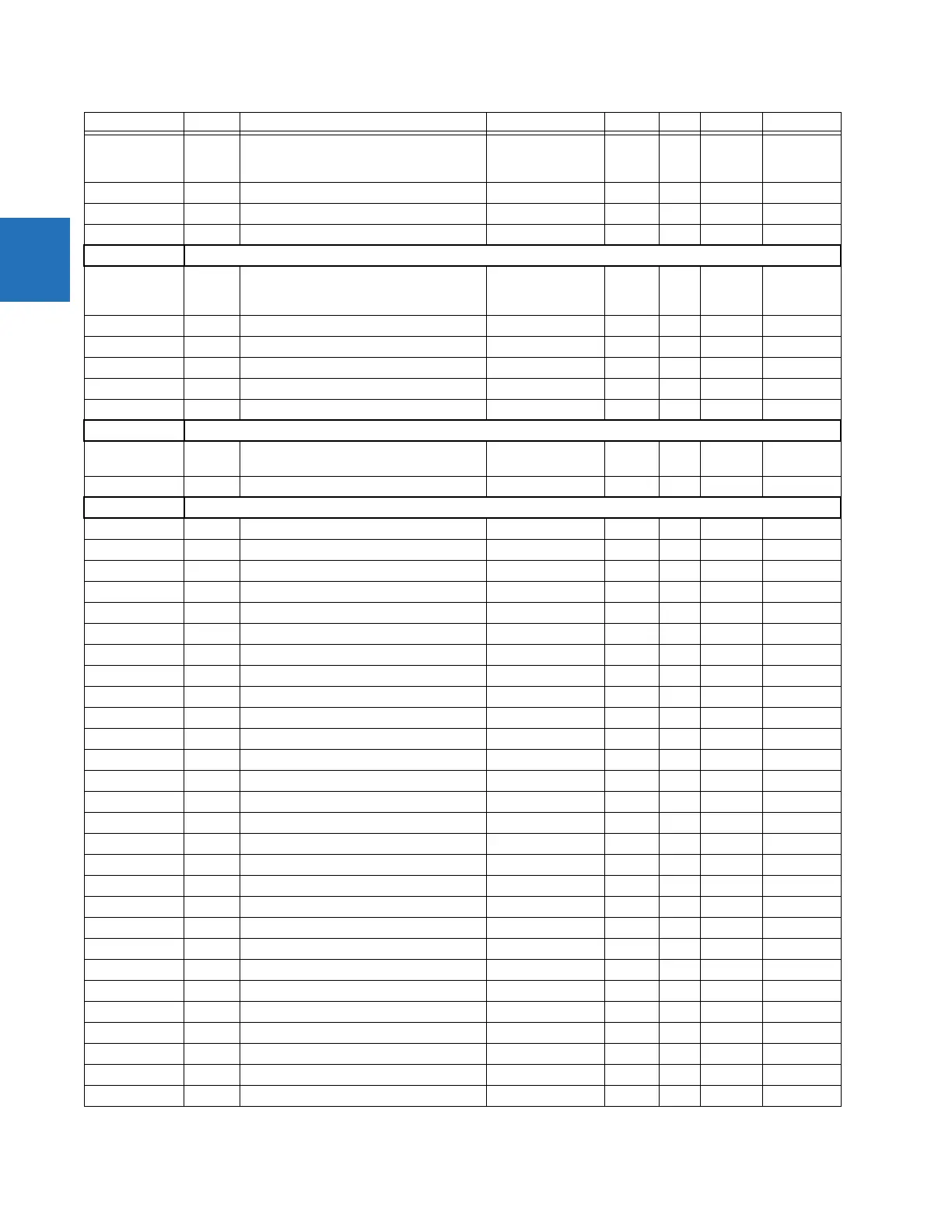
C60, D60, F35,
F60, L30, L60,
L90
2366 ...Repeated for Fault 2
F35, F60 238C ...Repeated for Fault 3
" 23B2 ...Repeated for Fault 4
" 23D8 ...Repeated for Fault 5
Autoreclose Status (Read Only) (1, 3, 4, or 6 Modules)
C60, D30, D60,
F35, F60, L30,
L60, L90
2410 Autoreclose 1 Count 0 to 65535 --- 1 F001 0
F35, F60, L30 2411 Autoreclose 2 Count 0 to 65535 --- 1 F001 0
" 2412 Autoreclose 3 Count 0 to 65535 --- 1 F001 0
F35, F60 2413 Autoreclose 4 Count 0 to 65535 --- 1 F001 0
F35 2414 Autoreclose 5 Count 0 to 65535 --- 1 F001 0
" 2415 Autoreclose 6 Count 0 to 65535 --- 1 F001 0
Field Unit Raw Data Settings (Read/Write Setting)
All except B90,
L60
2460 Field Raw Data Port 0 to 7 --- 1 F244 6 (H1a)
" 2461 Field Raw Data Freeze 0 to 1 --- 1 F102 0 (Disabled)
87L Current Differential Actual Values (Read Only)
L30, L90 2480 Local IA Magnitude 0 to 999999.999 A 0.001 F060 0
" 2482 Local IB Magnitude 0 to 999999.999 A 0.001 F060 0
" 2484 Local IC Magnitude 0 to 999999.999 A 0.001 F060 0
" 2486 Terminal 1 IA Magnitude 0 to 999999.999 A 0.001 F060 0
" 2488 Terminal 1 IB Magnitude 0 to 999999.999 A 0.001 F060 0
" 248A Terminal 1 IC Magnitude 0 to 999999.999 A 0.001 F060 0
" 248C Terminal 2 IA Magnitude 0 to 999999.999 A 0.001 F060 0
" 248E Terminal 2 IB Magnitude 0 to 999999.999 A 0.001 F060 0
" 2490 Terminal 2 IC Magnitude 0 to 999999.999 A 0.001 F060 0
" 2492 Differential Current IA Magnitude 0 to 999999.999 A 0.001 F060 0
" 2494 Differential Current IB Magnitude 0 to 999999.999 A 0.001 F060 0
" 2496 Differential Current IC Magnitude 0 to 999999.999 A 0.001 F060 0
" 2498 Local IA Angle -359.9 to 0 degrees 0.1 F002 0
" 2499 Local IB Angle -359.9 to 0 degrees 0.1 F002 0
" 249A Local IC Angle -359.9 to 0 degrees 0.1 F002 0
" 249B Terminal 1 IA Angle -359.9 to 0 degrees 0.1 F002 0
" 249C Terminal 1 IB Angle -359.9 to 0 degrees 0.1 F002 0
" 249D Terminal 1 IC Angle -359.9 to 0 degrees 0.1 F002 0
" 249E Terminal 2 IA Angle -359.9 to 0 degrees 0.1 F002 0
" 249F Terminal 2 IB Angle -359.9 to 0 degrees 0.1 F002 0
" 24A0 Terminal 2 IC Angle -359.9 to 0 degrees 0.1 F002 0
" 24A1 Differential Current IA Angle -359.9 to 0 degrees 0.1 F002 0
" 24A2 Differential Current IB Angle -359.9 to 0 degrees 0.1 F002 0
" 24A3 Differential Current IC Angle -359.9 to 0 degrees 0.1 F002 0
" 24A4 Op Square Current IA 0 to 999999.999 A 0.001 F060 0
" 24A6 Op Square Current IB 0 to 999999.999 A 0.001 F060 0
" 24A8 Op Square Current IC 0 to 999999.999 A 0.001 F060 0
" 24AA Restraint Square Current IA 0 to 999999.999 A 0.001 F060 0
Products Address Register name Range Units Step Format Default

 Loading...


