6-18 D60 Line Distance Protection System GE Multilin
6.3 METERING 6 ACTUAL VALUES
6
The metered phase voltage values are displayed in this menu. The "SRC 1" text will be replaced by whatever name was
programmed by the user for the associated source (see
SETTINGS SYSTEM SETUP SIGNAL SOURCES).
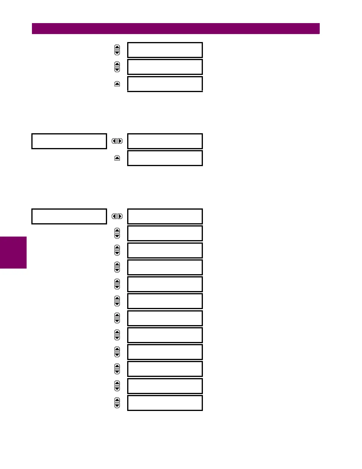
e) AUXILIARY VOLTAGE METERING
PATH: ACTUAL VALUES METERING SOURCE SRC 1 AUXILIARY VOLTAGE
The metered auxiliary voltage values are displayed in this menu. The "SRC 1" text will be replaced by whatever name was
programmed by the user for the associated source (see SETTINGS SYSTEM SETUP SIGNAL SOURCES).
f) POWER METERING
PATH: ACTUAL VALUES METERING SOURCE SRC 1 POWER
MESSAGE
SRC 1 ZERO SEQ V0:
0.000 V 0.0°
MESSAGE
SRC 1 POS SEQ V1:
0.000 V 0.0°
MESSAGE
SRC 1 NEG SEQ V2:
0.000 V 0.0°
AUXILIARY VOLTAGE
SRC 1
SRC 1 RMS Vx:
0.00 V
MESSAGE
SRC 1 PHASOR Vx:
0.000 V 0.0°
POWER
SRC 1
SRC 1 REAL POWER
3: 0.000 W
MESSAGE
SRC 1 REAL POWER
a: 0.000 W
MESSAGE
SRC 1 REAL POWER
b: 0.000 W
MESSAGE
SRC 1 REAL POWER
c: 0.000 W
MESSAGE
SRC 1 REACTIVE PWR
3: 0.000 var
MESSAGE
SRC 1 REACTIVE PWR
a: 0.000 var
MESSAGE
SRC 1 REACTIVE PWR
b: 0.000 var
MESSAGE
SRC 1 REACTIVE PWR
c: 0.000 var
MESSAGE
SRC 1 APPARENT PWR
3: 0.000 VA
MESSAGE
SRC 1 APPARENT PWR
a: 0.000 VA
MESSAGE
SRC 1 APPARENT PWR
b: 0.000 VA
MESSAGE
SRC 1 APPARENT PWR
c: 0.000 VA