GE Multilin D60 Line Distance Protection System 6-19
6 ACTUAL VALUES 6.3 METERING
6
The metered values for real, reactive, and apparent power, as well as power factor, are displayed in this menu. The "SRC
1" text will be replaced by whatever name was programmed by the user for the associated source (see
SETTINGS SYS-
TEM SETUP
SIGNAL SOURCES).
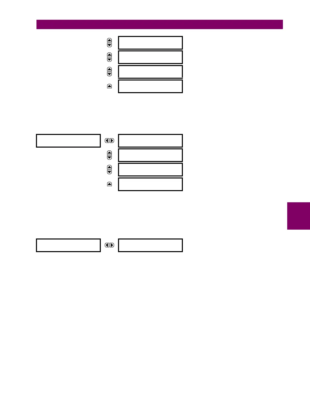
g) ENERGY METERING
PATH: ACTUAL VALUES METERING SOURCE SRC 1 ENERGY
The metered values for real and reactive energy are displayed in this menu. The "SRC 1" text will be replaced by whatever
name was programmed by the user for the associated source (see SETTINGS SYSTEM SETUP SIGNAL SOURCES).
Because energy values are accumulated, these values should be recorded and then reset immediately prior to changing
CT or VT characteristics.
h) FREQUENCY METERING
PATH: ACTUAL VALUES METERING SOURCE SRC 1 FREQUENCY
The metered frequency values are displayed in this menu. The "SRC 1" text will be replaced by whatever name was pro-
grammed by the user for the associated source (see
SETTINGS SYSTEM SETUP SIGNAL SOURCES).
SOURCE FREQUENCY is measured via software-implemented zero-crossing detection of an AC signal. The signal is either a
Clarke transformation of three-phase voltages or currents, auxiliary voltage, or ground current as per source configuration
(see the
SYSTEM SETUP POWER SYSTEM settings). The signal used for frequency estimation is low-pass filtered. The
final frequency measurement is passed through a validation filter that eliminates false readings due to signal distortions and
transients.
MESSAGE
SRC 1 POWER FACTOR
3: 1.000
MESSAGE
SRC 1 POWER FACTOR
a: 1.000
MESSAGE
SRC 1 POWER FACTOR
b: 1.000
MESSAGE
SRC 1 POWER FACTOR
c: 1.000
ENERGY
SRC 1
SRC 1 POS WATTHOUR:
0.000 Wh
MESSAGE
SRC 1 NEG WATTHOUR:
0.000 Wh
MESSAGE
SRC 1 POS VARHOUR:
0.000 varh
MESSAGE
SRC 1 NEG VARHOUR:
0.000 varh
FREQUENCY
SRC 1
SRC 1 FREQUENCY:
0.00 Hz