B-82 D60 Line Distance Protection System GE Multilin
B.4 MEMORY MAPPING APPENDIX B
B
D755 ...Repeated for Contact Output 60
D764 ...Repeated for Contact Output 61
D773 ...Repeated for Contact Output 62
D782 ...Repeated for Contact Output 63
D791 ...Repeated for Contact Output 64
DCmA Inputs (Read/Write Setting) (24 Modules)
D7A0 DCmA Inputs 1 Function 0 to 1 --- 1 F102 0 (Disabled)
D7A1 DCmA Inputs 1 ID --- --- --- F205 “DCMA I 1"
D7A7 Reserved 1 (4 items) 0 to 65535 --- 1 F001 0
D7AB DCmA Inputs 1 Units --- --- --- F206 “mA”
D7AE DCmA Inputs 1 Range 0 to 6 --- 1 F173 6 (4 to 20 mA)
D7AF DCmA Inputs 1 Minimum Value -9999.999 to 9999.999 --- 0.001 F004 4000
D7B1 DCmA Inputs 1 Maximum Value -9999.999 to 9999.999 --- 0.001 F004 20000
D7B3 ...Repeated for DCmA Inputs 2
D7C6 ...Repeated for DCmA Inputs 3
D7D9 ...Repeated for DCmA Inputs 4
D7EC ...Repeated for DCmA Inputs 5
D7FF ...Repeated for DCmA Inputs 6
D812 ...Repeated for DCmA Inputs 7
D825 ...Repeated for DCmA Inputs 8
D838 ...Repeated for DCmA Inputs 9
D84B ...Repeated for DCmA Inputs 10
D85E ...Repeated for DCmA Inputs 11
D871 ...Repeated for DCmA Inputs 12
D884 ...Repeated for DCmA Inputs 13
D897 ...Repeated for DCmA Inputs 14
D8AA ...Repeated for DCmA Inputs 15
D8BD ...Repeated for DCmA Inputs 16
D8D0 ...Repeated for DCmA Inputs 17
D8E3 ...Repeated for DCmA Inputs 18
D9F6 ...Repeated for DCmA Inputs 19
D909 ...Repeated for DCmA Inputs 20
D91C ...Repeated for DCmA Inputs 21
D92F ...Repeated for DCmA Inputs 22
D942 ...Repeated for DCmA Inputs 23
D955 ...Repeated for DCmA Inputs 24
DNP/IEC Points (Read/Write Setting)
D968 DNP/IEC 60870-5-104 Binary Input Points (256 items) 0 to 4294967295 --- 1 F300 0
DB68 DNP/IEC 60870-5-104 Analog Input Points (256 items) 0 to 65535 --- 1 F600 0
Synchrocheck (Read/Write Setting) (4 Modules)
DC70 Synchrocheck 1 Function 0 to 1 --- 1 F102 0 (Disabled)
DC71 Synchrocheck 1 V1 Source 0 to 5 --- 1 F167 0 (SRC 1)
DC72 Synchrocheck 1 V2 Source 0 to 5 --- 1 F167 1 (SRC 2)
DC73 Synchrocheck 1 Maximum Voltage Difference 0 to 400000 V 1 F060 10000
DC75 Synchrocheck 1 Maximum Angle Difference 0 to 100 degrees 1 F001 30
DC76 Synchrocheck 1 Maximum Frequency Difference 0 to 2 Hz 0.01 F001 100
DC77 Synchrocheck 1 Dead Source Select 0 to 5 --- 1 F176 1 (LV1 and DV2)
DC78 Synchrocheck 1 Dead V1 Maximum Voltage 0 to 1.25 pu 0.01 F001 30
DC79 Synchrocheck 1 Dead V2 Maximum Voltage 0 to 1.25 pu 0.01 F001 30
DC7A Synchrocheck 1 Live V1 Minimum Voltage 0 to 1.25 pu 0.01 F001 70
DC7B Synchrocheck 1 Live V2 Minimum Voltage 0 to 1.25 pu 0.01 F001 70
DC7C Synchrocheck 1 Target 0 to 2 --- 1 F109 0 (Self-reset)
DC7D Synchrocheck 1 Events 0 to 1 --- 1 F102 0 (Disabled)
DC7E Synchrocheck 1 Block 0 to 4294967295 --- 1 F300 0
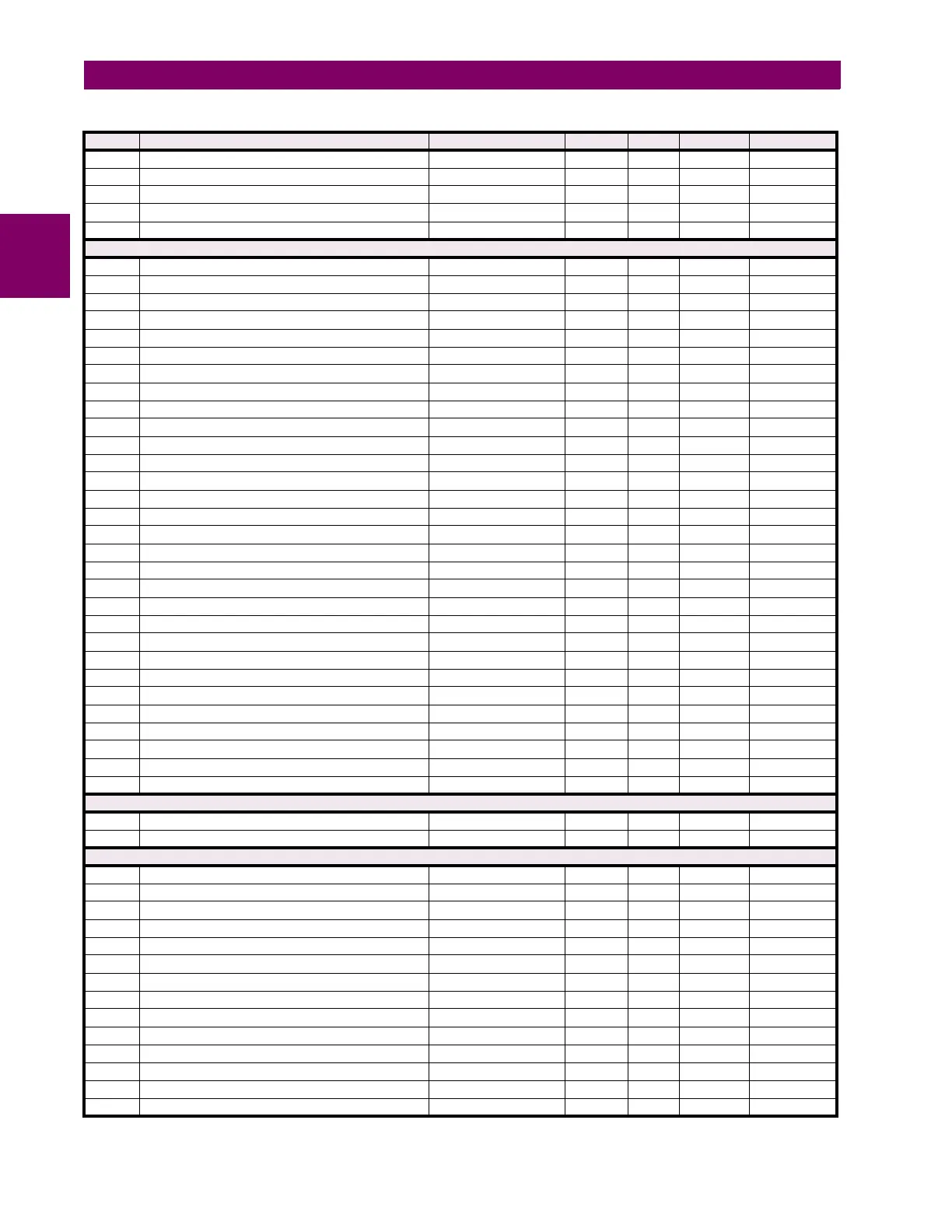
Table B–10: MODBUS MEMORY MAP (Sheet 74 of 77)
ADDR REGISTER NAME RANGE UNITS STEP FORMAT DEFAULT