EasyManuals Logo

GE Evolution E9000 Series User Manual

GE Evolution E9000 Series
52 pages
To Next Page IconTo Next Page
To Previous Page IconTo Previous Page
Page #11 background imageLoading...
Page #11 background image
INSTALLATION, OPERATIONS AND MAINTENANCE MANUAL 11

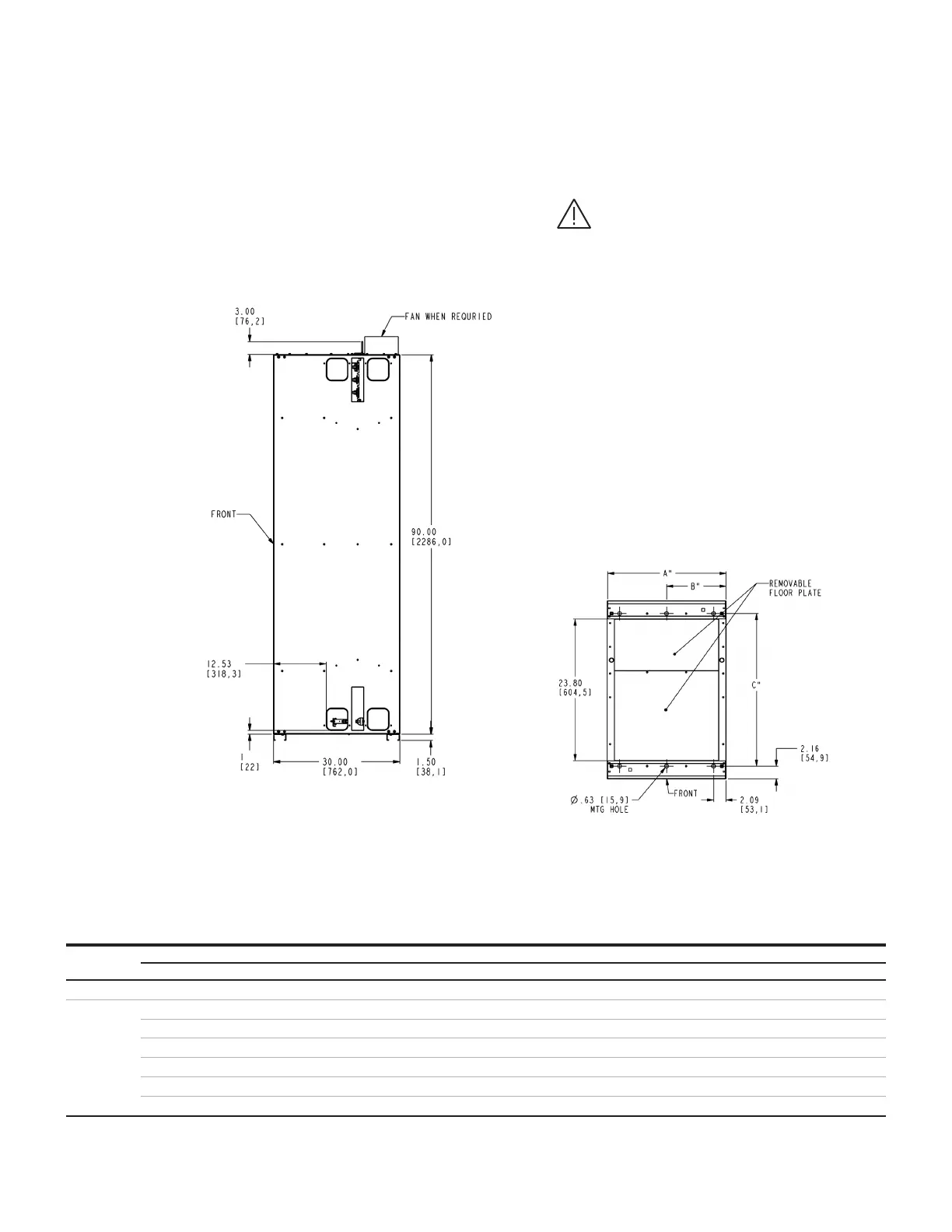
1. If anchor bolts are to be inbedded in
the foundation, they must be located
according to the drawing for the specific
equipment. Locate one in the center front
and one in the center back. Anchor bolts

steel (minimum) In non-Seismic Zone 4
Locations. Bolts must extend a minimum
of 2 11/32 inch above grade to 3/4 inch
above the channel sill. If 13 (330.2mm)
deep verical sections are used, anchor
bolts or some form of external bracing
is required.
2. Seismic IBC testing was performed use

foot-pounds, located in each of the
four corners in each section.
REF.
DIM.
Section Depth
    
Width "A" B C B C B C B C B C
          
          
          
          
          
          
Indoor enclosures
Elevation and Mounting
30-inch Deep Sections 600 A to 1200 A Main Bus
Bottom view: Location of mounting holes
End view: Standard 30-inch deep

Questions and Answers:

Question and Answer IconNeed help?

Do you have a question about the GE Evolution E9000 Series and is the answer not in the manual?

GE Evolution E9000 Series Specifications

General IconGeneral
BrandGE
ModelEvolution E9000 Series
CategoryControl Unit
LanguageEnglish

Related product manuals