12 EVOLUTION SERIES E9000 MOTOR CONTROL CENTER
—
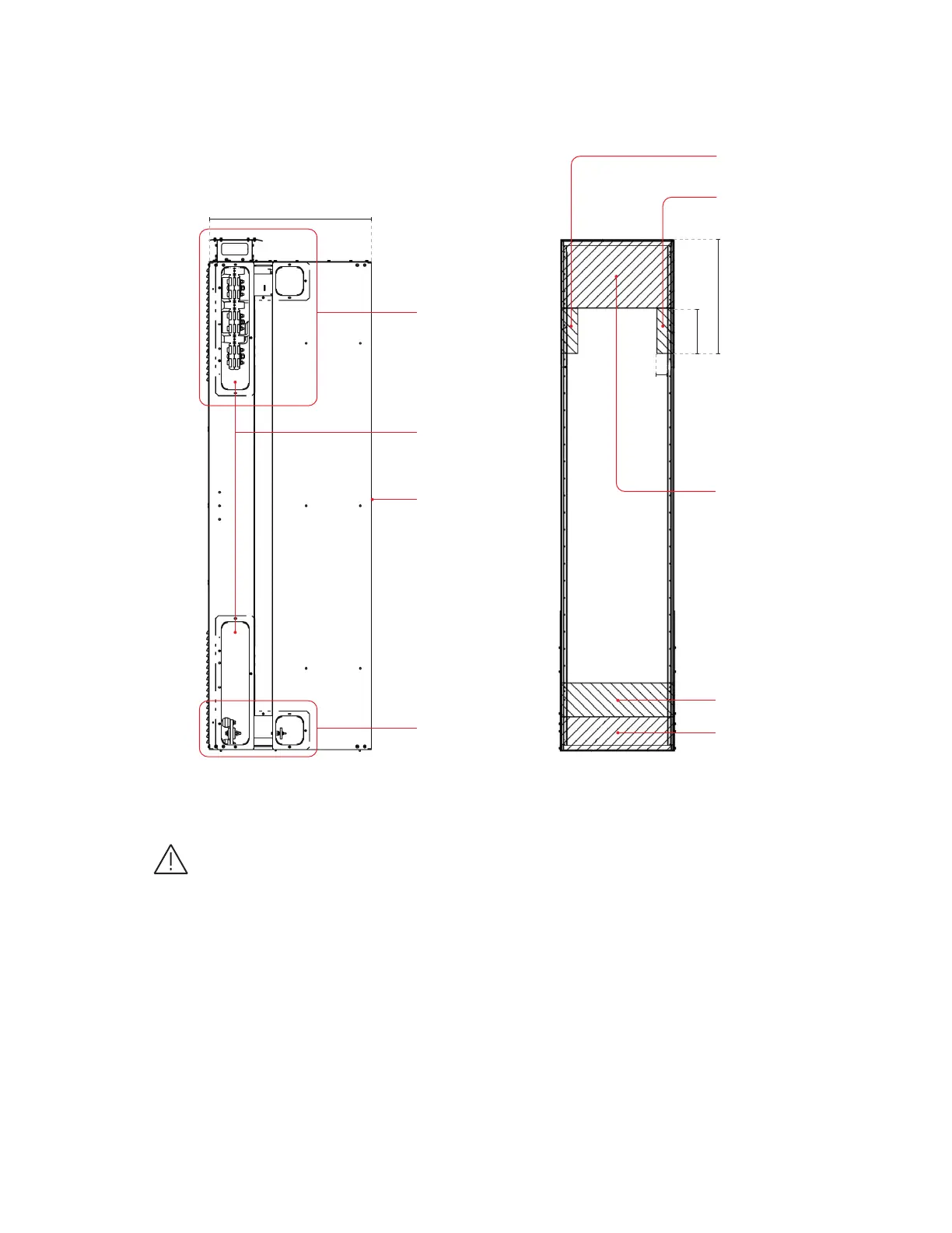
End view: Standard 30-inch deep section for 2500A without
fans, 3000A, and 3200A main bus configurations
Front
See Detail D
See Detail D
Removable end plates
cover wire trough and
bus extension openings
Deep 30.0
Side view
End plate cover
—
Restricted zones - No component can be placed
in restricted zones as shown in figure.
Indoor enclosures
Elevation and mounting
30-inch deep sections 2500A without fans,
3000A, and 3200A main bus configurations.
1. If anchor bolts are to be inbedded in the
foundation, they must be located according to
the drawing for the specific equipment. Locate
one in the center front and one in the center back.
Anchor bolts should be 1/2 inch diameter, of
Locations.
Restricted 12" wireway zone
12"
20"
Restricted 12" wireway zone
Optional zone
splice bolt acces
Restricted zone
splice bolt acces
Restricted 6" feeders wireway zone
3"
Bolts must extend a minimum of 2 11/32 inch
above grade to 3/4 inch above the channel sill.
If 13 (330.2mm) deep verical sections are used,
anchor bolts or some form of external bracing
is required.
2. Seismic IBC testing was performed use
foot-pounds, located in each