3-50 G60 Generator Protection System GE Multilin
3.4 FIELD AND STATOR GROUND MODULES 3 HARDWARE
3
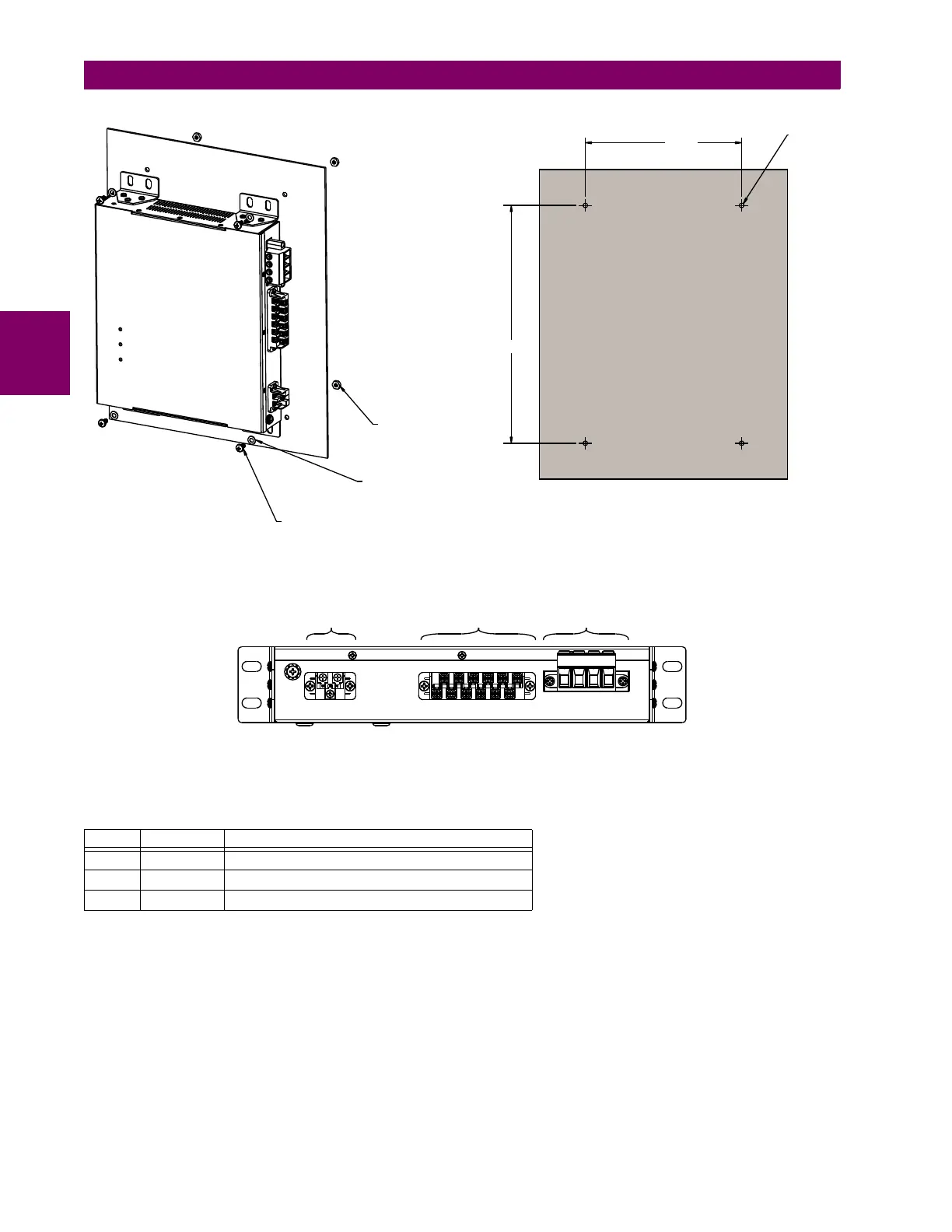
Figure 3–53: MOUNTING DIAGRAM FOR GPM-F-L WALL-MOUNTED UNIT
There are three connectors on the field protection low-voltage module as shown in the following figure.
Figure 3–54: REAR VIEW OF GPM-F-L MODULE SHOWING TERMINAL BLOCKS
The following tables outline the pin assignments.
Table 3–5: GPM-F-L PIN ASSIGNMENTS FOR CONNECTOR A
PIN LABEL DEFINITION
1 L(+) AC-L (DC+)
2 N(–) AC-N (DC–)
3 GND Ground
1XW1\ORFN
=LQF
*(31
47<
:DVKHUIODW=LQF
*(31
47<
6FUHZîµ3DQ+'=LQF
*(3147<
$&'5
î
&RQQHFWRU$ &RQQHFWRU% &RQQHFWRU&
$&'5