GE Multilin G60 Generator Protection System 3-65
3 HARDWARE 3.4 FIELD AND STATOR GROUND MODULES
3
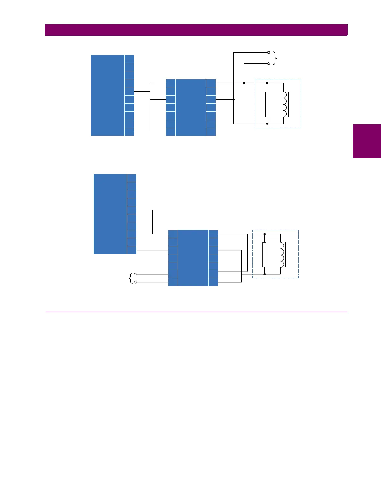
Figure 3–73: STATOR GROUND PROTECTION SYSTEM CONNECTIONS (NGT SECONDARY ≤ 240 V)
The following figure illustrates how to connect the stator ground 20 Hz generator module with the band pass filter module
where the NGT secondary voltage is greater than 240 V.
Figure 3–74: STATOR GROUND PROTECTION SYSTEM CONNECTIONS (NGT SECONDARY > 240 V)
3.4.5 UPGRADING FIRMWARE
a) UPGRADING THE GPM-F FIRMWARE
The following procedure describes how the upgrade the firmware for the GPM-F modules. Do the upgrade using the front
port and one of the computer COM ports 1 to 4.
6WDWRUJURXQG
EDQGSDVV
ILOWHUPRGXOH
*306%
$
$
$
6WDWRU
JURXQG
+]
JHQHUDWRU
PRGXOH
*306*
$
$
$
$
$
$
$
$
$
$
5
Q
WR*
DX[LOLDU\97
$&'5
$
$
$
$
%
%
%
%
%
%
%
Stator ground
band pass
filter module
GPM-S-B
A1
A2
A3
Stator
ground
20 Hz
generator
module
GPM-S-G
A5
A6
A7
A8
A9
A10
A1
A2
A3
A4
R
n
830757A3.CDR
A4
A5
A6
A7
B1
B2
B3
B4
B5
B6
B7
to G60
auxiliary VT