5-308 G60 Generator Protection System GE Multilin
5.8 INPUTS/OUTPUTS 5 SETTINGS
5
GOOSE Analogs that represent current, voltage, power, frequency, angles, or power factor can be used in a FlexEle-
ment. The following text must be used in the UNITS setting, to represent these types of analogs: A, V, W, var, VA, Hz,
deg, and no text (blank setting) for power factor.
GOOSE Analogs can be compared to other GOOSE Analogs with any character string or no string.
• GOOSE ANALOG 1 PU: This setting specifies the per-unit base factor when using the GOOSE analog input FlexAna-
log values in other G60 features, such as FlexElements. The base factor is applied to the GOOSE analog input Flex-
Analog quantity to normalize it to a per-unit quantity. The base units are described in the following table.
The per-unit base setting represents thousands, not single units. For example, a PU base of 1.000 is actually 1000 and
a PU base of 0.001 is 1.
When using GOOSE Analogs and PU base in FlexElements, the largest value that can be displayed in the FlexEle-
ment actual values is 2,140,000.000.
The GOOSE analog input FlexAnalog values are available for use in other G60 functions that use FlexAnalog values.
5.8.13 IEC 61850 GOOSE INTEGERS
PATH: SETTINGS INPUTS/OUTPUTS IEC 61850 GOOSE UINTEGERS GOOSE UINTEGER INPUT 1(16)
The IEC 61850 GOOSE uinteger inputs feature allows the transmission of FlexInteger values between any two UR-series
devices. The following settings are available for each GOOSE uinteger input.
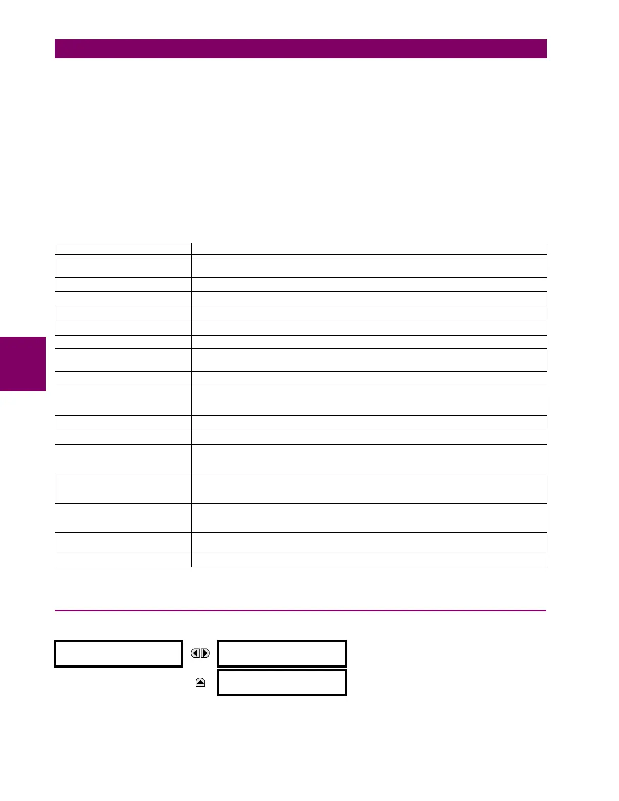
Table 5–35: GOOSE ANALOG INPUT BASE UNITS
ELEMENT BASE UNITS
DCmA BASE = maximum value of the
DCMA INPUT MAX setting for the two transducers configured
under the +IN and –IN inputs.
FREQUENCY f
BASE
= 1 Hz
FREQUENCY RATE OF CHANGE df/dt
BASE
= 1 Hz/s
PHASE ANGLE ϕ
BASE
= 360 degrees (see the UR angle referencing convention)
POWER FACTOR PF
BASE
= 1.00
RTDs BASE = 100°C
SENSITIVE DIR POWER
(Sns Dir Power)
P
BASE
= maximum value of 3 × V
BASE
× I
BASE
for the +IN and –IN inputs of the sources
configured for the sensitive power directional element(s).
SOURCE CURRENT I
BASE
= maximum nominal primary RMS value of the +IN and –IN inputs
SOURCE ENERGY
(Positive and Negative Watthours,
Positive and Negative Varhours)
E
BASE
= 10000 MWh or MVAh, respectively
SOURCE POWER P
BASE
= maximum value of V
BASE
× I
BASE
for the +IN and –IN inputs
SOURCE VOLTAGE V
BASE
= maximum nominal primary RMS value of the +IN and –IN inputs
STATOR DIFFERENTIAL
CURRENT
(Stator Diff Iar, Ibr, and Icr)
I
BASE
= maximum primary RMS value of the +IN and –IN inputs
(CT primary for source currents, and bus reference primary current for bus differential currents)
STATOR GROUND 3RD
HARMONIC VOLTAGES
(Stator Gnd Vn/V0 3rd)
V
BASE
= Primary auxiliary voltage of the STATOR GROUND SOURCE
STATOR RESTRAINING
CURRENT
(Stator Diff Iad, Ibd, and Icd)
I
BASE
= maximum primary RMS value of the +IN and –IN inputs
(CT primary for source currents, and bus reference primary current for bus differential currents)
SYNCHROCHECK
(Max Delta Volts)
V
BASE
= maximum primary RMS value of all the sources related to the +IN and –IN inputs
VOLTS PER HERTZ BASE = 1.00 pu
GOOSE UINTEGER
INPUT 1
UINTEGER 1 DEFAULT:
1000
Range: 0 to 429496295 in steps of 1
MESSAGE
UINTEGER 1 DEFAULT
MODE: Default Value
Range: Default Value, Last Known