GE Multilin G60 Generator Protection System 8-1
8 THEORY OF OPERATION 8.1 PHASE DISTANCE THROUGH POWER TRANSFORMERS
8
8 THEORY OF OPERATION 8.1PHASE DISTANCE THROUGH POWER TRANSFORMERS 8.1.1 DESCRIPTION
As a Wye-Delta transformer introduces discontinuity for the zero-sequence circuit, the ground distance protection cannot
be applied, except special circumstances, to respond to faults behind the transformer.
The phase distance elements, however, could be developed so that both accurate reach and correct fault phase identifica-
tion is retained for faults behind the power transformer as seen from the relaying point. Without appropriate compensation,
the relay's reach would depend on a type of fault, creating considerable difficulties in applying the relay.
The G60 provides for any location of the VTs and CTs with respect to the involved power transformer and the direction of
any given zone.
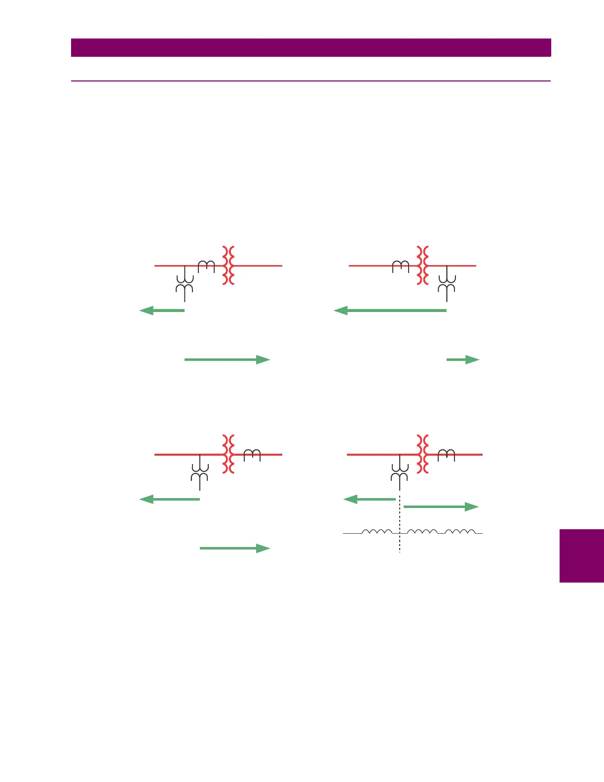
In the following equations, the VT and CT locations are referenced as “None” if the transformer is not present between the
CT/VT and the intended reach point. Otherwise, the location is to be selected as a type of a transformer as seen from the
VT/CT position towards the intended reach point. The following figure explains the adopted rules.
Figure 8–1: APPLICATIONS OF THE “PHS DIST XFMR VOL/CUR CONNECTION” SETTINGS
830717A1.CDR
Z1
Z3
Z3XFRM VOL CONNECTION=None
Z3XFRM CUR CONNECTION=None
Z1XFRM VOL CONNECTION=Dy11
Z1XFRM CUR CONNECTION=Dy11
delta wye, 330
o
lag
(a)
Z1
Z3
Z3XFRM VOL CONNECTION=Yd1
Z3XFRM CUR CONNECTION=None
Z1XFRM VOL CONNECTION=None
Z1XFRM CUR CONNECTION=Dy11
delta wye, 330
o
lag
(b)
Z1
Z3
Z3XFRM VOL CONNECTION=None
Z3XFRM CUR CONNECTION=Yd1
Z1XFRM VOL CONNECTION=Dy11
Z1XFRM CUR CONNECTION=None
delta wye, 330
o
lag
(c)
Zone 1
Zone 3
(e)
L
1
L
2
Z
L1
Z
T
Z
L2