3-64 G60 Generator Protection System GE Multilin
3.4 FIELD AND STATOR GROUND MODULES 3 HARDWARE
3
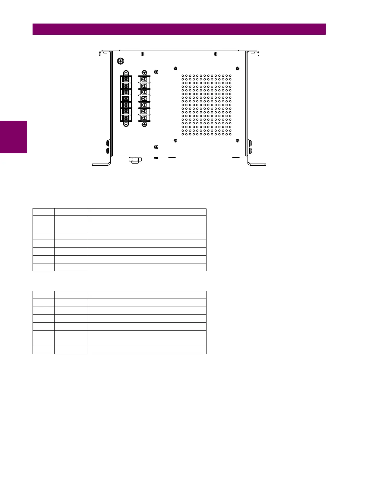
Figure 3–72: GPM-S-B MODULE SHOWING TERMINAL BLOCKS
The following tables outline the pin assignments.
The following figure illustrates how to connect the stator ground 20 Hz generator module with the band pass filter module
where the neutral grounding transformer (NGT) secondary voltage is less than or equal to 240 V.
Table 3–16: GPM-S-B PIN ASSIGNMENTS FOR CONNECTOR A
PIN LABEL DEFINITION
1 A1 Input 1
2 A2 Not used
3 A3 Input 2
4 A4 Not used
5A5 Reserved
6 A6 Divider out
7 A7 Divider low
Table 3–17: GPM-S-B PIN ASSIGNMENTS FOR CONNECTOR B
PIN LABEL DEFINITION
1 B1 Output 1
2 B2 Not used
3 B3 Output 2
4 B4 Not used
5B5 Reserved
6 B6 Divider high
7 B7 Divider low
$%
$&'5