GE Multilin G60 Generator Protection System 3-63
3 HARDWARE 3.4 FIELD AND STATOR GROUND MODULES
3
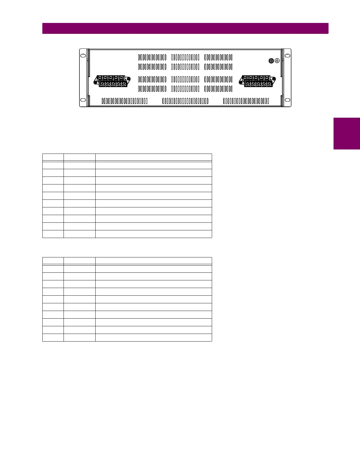
Figure 3–71: REAR VIEW OF GPM-S-G MODULE SHOWING TERMINAL BLOCKS
The following tables outline the pin assignments for the stator ground 20 Hz generator module. Two contact inputs are pro-
vided. Upon closure of any one of the contact inputs, 20 Hz injection stops.
There are two connectors on the stator ground protection band pass filter module, as shown in the following figure.
Table 3–14: GPM-S-G PIN ASSIGNMENTS FOR CONNECTOR A
PIN LABEL DEFINITION
1 A1 Contact input 1
2 A2 Contact input 2
3 A3 Alarm relay NC (normally closed)
4 A4 Not used
5 A5 Output 1
6 A6 Contact input common
7 A7 Alarm relay NO (normally open)
8 A8 Alarm relay common
9 A9 Not used
10 A10 Output 2
Table 3–15: GPM-S-G PIN ASSIGNMENTS FOR CONNECTOR B
PIN LABEL DEFINITION
1 B1 Not used
2 B2 Not used
3 B3 Not used
4 B4 Not used
5 B5 Not used
6 B6 Not used
7 B7 Not used
8 B8 Ground
9 B9 Power neutral / DC negative
10 B10 Power line / DC positive
$&'5
$%

 Loading...


