3-56 G60 Generator Protection System GE Multilin
3.4 FIELD AND STATOR GROUND MODULES 3 HARDWARE
3
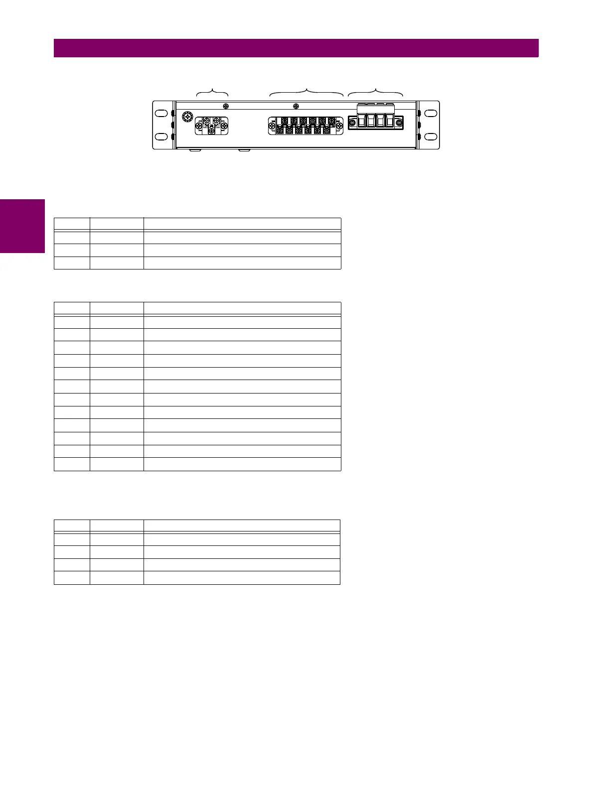
Figure 3–62: REAR VIEW OF GPM-F-HM MODULE SHOWING TERMINAL BLOCKS
The following tables outline the pin assignments.
Three contact inputs are provided. Upon closure of any one of the contact inputs, low frequency injection stops.
There are three connectors on the field ground protection high-voltage resistor box, as shown in the following figure.
Table 3–8: GPM-F-HM PIN ASSIGNMENTS FOR CONNECTOR A
PIN LABEL DEFINITION
1 L(+) AC-L (DC+)
2 N(–) AC-N (DC–)
3 GND Ground
Table 3–9: GPM-F-HM PIN ASSIGNMENTS FOR CONNECTOR B
PIN LABEL DEFINITION
1 CH1(+) RS485 channel 1 positive
2 CH1(–) RS485 channel 1 negative
3 COM RS485 common
4 CH2(+) RS485 channel 2 positive
5 CH2(–) RS485 channel 2 negative
6 IN3 Contact input 3
7 IN2 Contact input 2
8 IN1 Contact input 1
9 COM Contact input common
10 NC Relay NC (normally closed)
11 COM Relay common
12 NO Relay NO (normally open)
Table 3–10: GPM-F-HM PIN ASSIGNMENTS FOR CONNECTOR C
PIN LABEL DEFINITION
1 FGND Field ground
2 F1 Injection to excitation positive
3 F(–) Injection to excitation negative / excitation negative
4 F(+) Excitation positive
&RQQHFWRU$ &RQQHFWRU% &RQQHFWRU&
$&'5

 Loading...


