5-30 G60 Generator Protection System GE Multilin
5.2 PRODUCT SETUP 5 SETTINGS
5
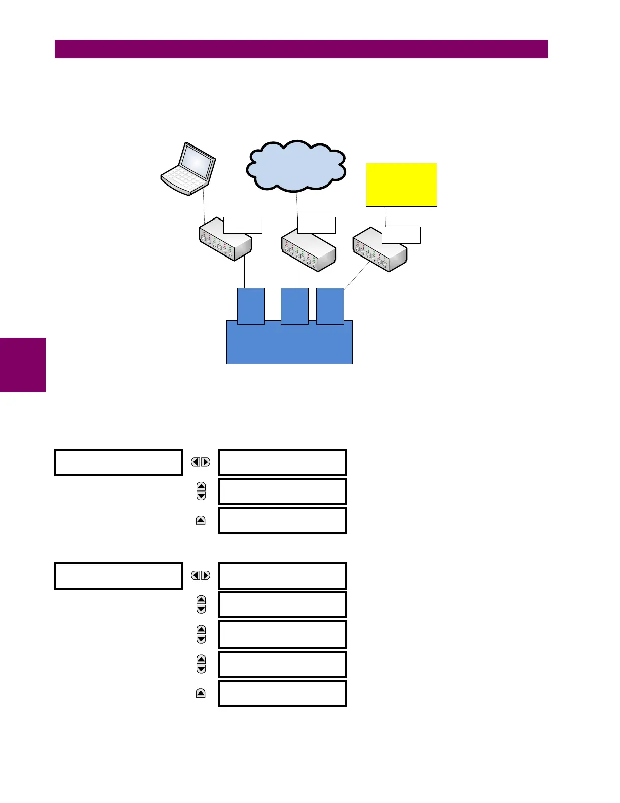
Multiple LANS, No Redundancy
The following topology provides local configuration/monitoring through EnerVista software on LAN1, to which port 1 (P1) is
connected, access to the public network on LAN2, to which port 2 (P2) is connected and communications with SCADA on
LAN3, to which port 3 (P3) is connected. There is no redundancy.
Figure 5–6: MULTIPLE LANS, NO REDUNDANCY
d) NETWORK
As outlined in the previous section, when using more than one Ethernet port, configure each to belong to a different net-
work or subnet using the IP addresses and mask. Configure the network IP and subnet settings before configuring the rout-
ing settings.
PATH: SETTINGS PRODUCT SETUP COMMUNICATIONS NETWORK 1(3)
NETWORK PORT 1
PRT1 IP ADDRESS:
127.0.0.1
Range: Standard IPV4 address format
MESSAGE
PRT1 SUBNET IP MASK:
255.0.0.0
Range: Standard IPV4 address format
MESSAGE
PRT1 GOOSE ENABLED:
Enabled
Range: Enabled, Disabled
NETWORK PORT 2
PRT2 IP ADDRESS:
127.0.0.1
Range: Standard IPV4 address format
MESSAGE
PRT2 SUBNET IP MASK:
255.0.0.0
Range: Standard IPV4 address format
MESSAGE
PRT2 REDUNDANCY:
None
Range: None, Failover, PRP
None, Failover (if no PRP license)
MESSAGE
PRT2 PRP MCST ADDR:
01-15-4E-00-01-00
Range: 01-15-4E-00-01-00 to 01-15-4E-00-01-FF
MESSAGE
PRT2 GOOSE ENABLED:
Enabled
Range: Enabled, Disabled
EnerVista Software
ML3000
Public Network
SCADA
UR
P1
IP1/
MAC1
P2
IP2/
MAC2
ML3000
ML3000
LAN1 LAN2
LAN3
P3
IP3/
MAC3
859710A2.vsd