5-114 G60 Generator Protection System GE Multilin
5.4 SYSTEM SETUP 5 SETTINGS
5
Firmware versions 7.0 and above have a 90-5 based R-SV implementation equivalent in structure and configuration to that
of the existing C37.118 implementation of firmware version 6.0, that is, synchrophasor data at rates up to 60 Hz for meter-
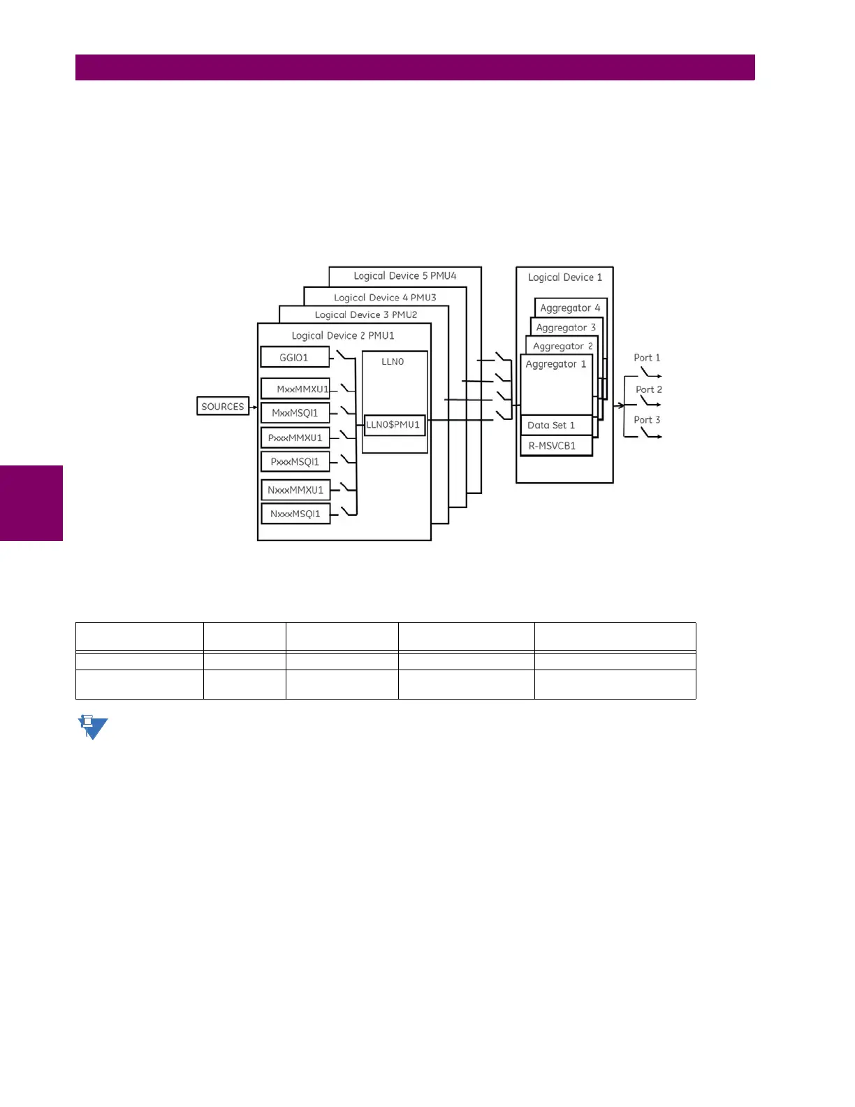
ing and 120 Hz for protection class synchrophasors. The two figures below depict the general data flow for the generation
of synchrophasor data for IEC61850-90-5. In the first figure, when IEC61850-90-5 is selected all real and virtual sources
are available for the IEC61850-90-5 PMUs.
Firmware version 7.0 allows the N60 to support a maximum of four Logical Device PMUs (Logical Device 2 through 5) and
four aggregators (located in Logical Device 1 (LD1)), while other UR family members support one PMU and only one
aggregator. The control blocks for the aggregators are located in LD1. A 64 char LDName setting is provided, see figure
below..
Figure 5–41: N60 SUPPORT FOR FOUR LOGICAL DEVICE PMUS
The specifics of implementation by model number is summarized in the table below.
Precise time input to the relay from the international time standard, via either IRIG-B or PTP, is vital for correct syn-
chrophasor measurement and reporting. For IRIG-B, a DC level shift IRIG-B receiver must be used for the phasor
measurement unit to output proper synchrophasor values.
Table 5–11: IMPLEMENTATION BY MODEL NUMBER
MODEL NUMBER OF
PMUS
NUMBER OF
AGGREGATORS
NUMBER OF ANALOG
INPUTS
COMMENT
N60 4 4 16 1, 2, or 4 PMUs can be used
D60, F60, G60, L30,
L90, T60
11 16