5-178 G60 Generator Protection System GE Multilin
5.6 GROUPED ELEMENTS 5 SETTINGS
5
SATURATION DETECTION:
External faults near generators typically result in very large time constants of DC components in the fault currents. Also,
when energizing a step-up transformer, the inrush current being limited only by the machine impedance may be significant
and may last for a very long time. In order to provide additional security against maloperations during these events, the G60
incorporates saturation detection logic. When saturation is detected the element will make an additional check on the angle
between the neutral and output current. If this angle indicates an internal fault then tripping is permitted.
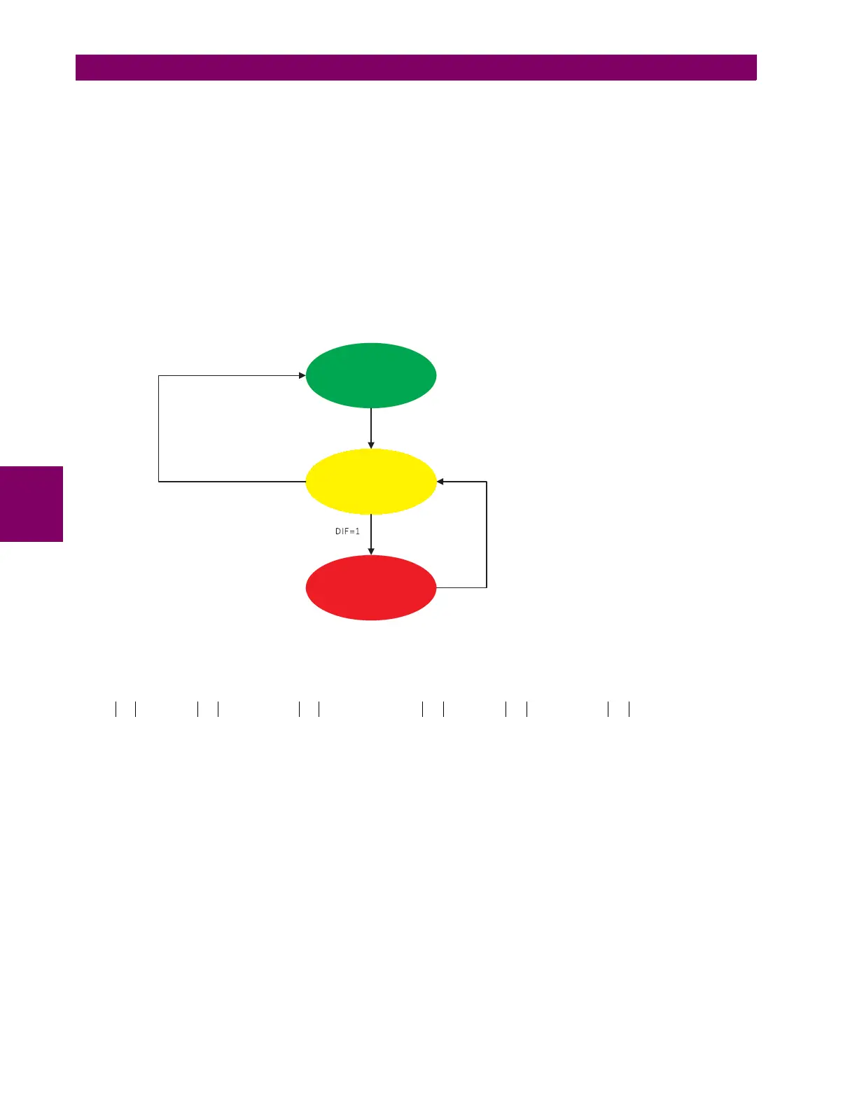
The saturation detector is implemented as a state machine (see below). "NORMAL" is the initial state of the machine.
When in "NORMAL" state, the saturation flag is not set (SAT = 0). The algorithm calculates the saturation condition, SC. If
SC = 1 while the state machine is "NORMAL", the saturation detector goes into the "EXTERNAL FAULT" state and sets the
saturation flag (SAT = 1). The algorithm returns to the "NORMAL" state if the differential current is below the first slope, SL,
for more than 200 ms. When in the "EXTERNAL FAULT" state, the algorithm goes into the "EXTERNAL FAULT & CT SAT-
URATION" state if the differential flag is set (DIF = 1). When in the "EXTERNAL FAULT & CT SATURATION" state, the
algorithm keeps the saturation flag set (SAT = 1). The state machine returns to the "EXTERNAL FAULT" state if the differ-
ential flag is reset (DIF = 0) for 100 ms.
Figure 5–82: SATURATION DETECTION STATE MACHINE
PHASE COMPARISON PRINCIPLE:
The test for direction can be summarized by the following equation:
(EQ 5.7)
where: I
R
= restraining current, DIR = flag indicating that the phase comparison principle is satisfied
B
L
= breakpoint 1 setting, I
TS
, I
NS
= current at the terminal and neutral sources, respectively
K = factory constant of 0.25
830736A1.CDR
NORMAL
SAT:=0
SC
(saturation condition)
EXTERNAL FAULT
SAT:=1
EXTERNAL FAULT
AND CT SATURATION
SAT:=1
DIF = 0
for 100 ms
(|ID| < SL x IR) or (|ID| < PICKUP)
AND
(NOT (SC)) for 200 ms
SC = (|ID| < SL x IR) and (IR > BL)
where:
IR = restraint current
ID = differential current
DIF = stator differential pickup flag
SL = slope 1 setting
BL = break point 1 setting
PICKUP = pickup setting
If I
TS
B
L
> or I
TS
KI
R
⋅> and I
TS
0.1 pu>()() and I
NS
B
L
> or I
NS
KI
R
⋅> and I
NS
0.1 pu>()()
then DIR abs I
TS
∠ I
NS
∠–()90°>=
else DIR 1=