2-2 G60 Generator Protection System GE Multilin
2.1 INTRODUCTION 2 PRODUCT DESCRIPTION
2
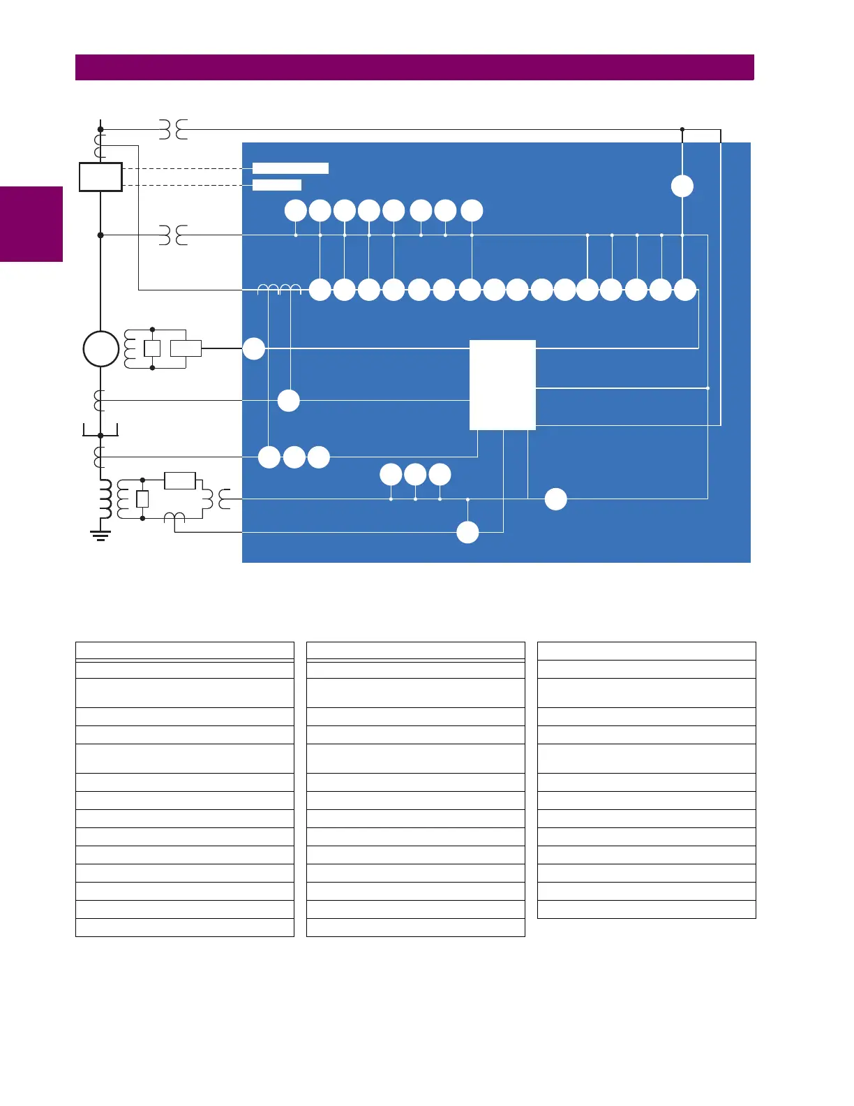
Figure 2–1: SINGLE LINE DIAGRAM
Table 2–2: OTHER DEVICE FUNCTIONS
FUNCTION FUNCTION FUNCTION
Breaker control Event recorder Synchrophasors
Breaker flashover FlexLogic equations Time synchronization over IRIG-B or IEEE
1588
Contact inputs (up to 96) FlexElements™ (16) Time synchronization over SNTP
Contact outputs (up to 64) IEC 61850 communications (optional) Transducer inputs and outputs
Control pushbuttons Metering: current, voltage, power,
frequency
Trip output
CT failure detector Oscillography User-definable displays
CyberSentry™ security Modbus communications User-programmable fault reports
Data logger Modbus user map User-programmable LEDs
Digital counters (8) Non-volatile latches User-programmable pushbuttons
Digital elements (48) Non-volatile selector switch User-programmable self-tests
Direct inputs and outputs (32) RTD protection Virtual inputs (64)
Disconnect switches Remote RTD protection Virtual outputs (96)
DNP 3.0 or IEC 60870-5-104 protocol Setting groups (6) VT fuse failure
Ethernet Global Data protocol (optional) Stator differential
830710B6.CDR
50G87RGF 51G
64TN
51PV 51N
46
67P 67N67_2
68 78
24
59P
27P
59_2
25
Metering
Trip
Supervised Close
32
50/27
40
59N
81U
81O
27TN
59X27X
G60 Generator Protection System
52
R
87S
81R
50N
21P
G
64S
EX GPM-F
64F
GPM-S
50P 50BF
49