GE Multilin G60 Generator Protection System 5-201
5 SETTINGS 5.6 GROUPED ELEMENTS
5
The equation above brings an advantage of generating the restraining signal of twice the external ground fault current,
while reducing the restraint below the internal ground fault current. The negative-sequence component of the restraining
signal (IR2) is meant to provide maximum restraint during external phase-to-phase faults and is calculated as follows:
(EQ 5.21)
Following complete de-energization of the windings (all three phase currents below 5% of nominal for at least five cycles),
the relay uses a multiplier of 1 in preparation for the next energization. The multiplier of 3 is used during normal operation;
that is, two cycles after the winding has been energized. The lower multiplier is used to ensure better sensitivity when ener-
gizing a faulty winding.
The positive-sequence component of the restraining signal (IR1) is meant to provide restraint during symmetrical condi-
tions, either symmetrical faults or load, and is calculated according to the following algorithm:
1 If of phase CT, then
2 If , then
3else
4else
Under load-level currents (below 150% of nominal), the positive-sequence restraint is set to 1/8th of the positive-sequence
current (line 4). This is to ensure maximum sensitivity during low-current faults under full load conditions. Under fault-level
currents (above 150% of nominal), the positive-sequence restraint is removed if the zero-sequence component is greater
than the positive-sequence (line 3), or set at the net difference of the two (line 2).
The raw restraining signal (Irest) is further post-filtered for better performance during external faults with heavy CT satura-
tion and for better switch-off transient control:
(EQ 5.22)
where k represents a present sample, k – 1 represents the previous sample, and α is a factory constant (α<1). The equa-
tion above introduces a decaying memory to the restraining signal. Should the raw restraining signal (Irest) disappear or
drop significantly, such as when an external fault gets cleared or a CT saturates heavily, the actual restraining signal (Igr(k))
will not reduce instantly but will keep decaying decreasing its value by 50% each 15.5 power system cycles.
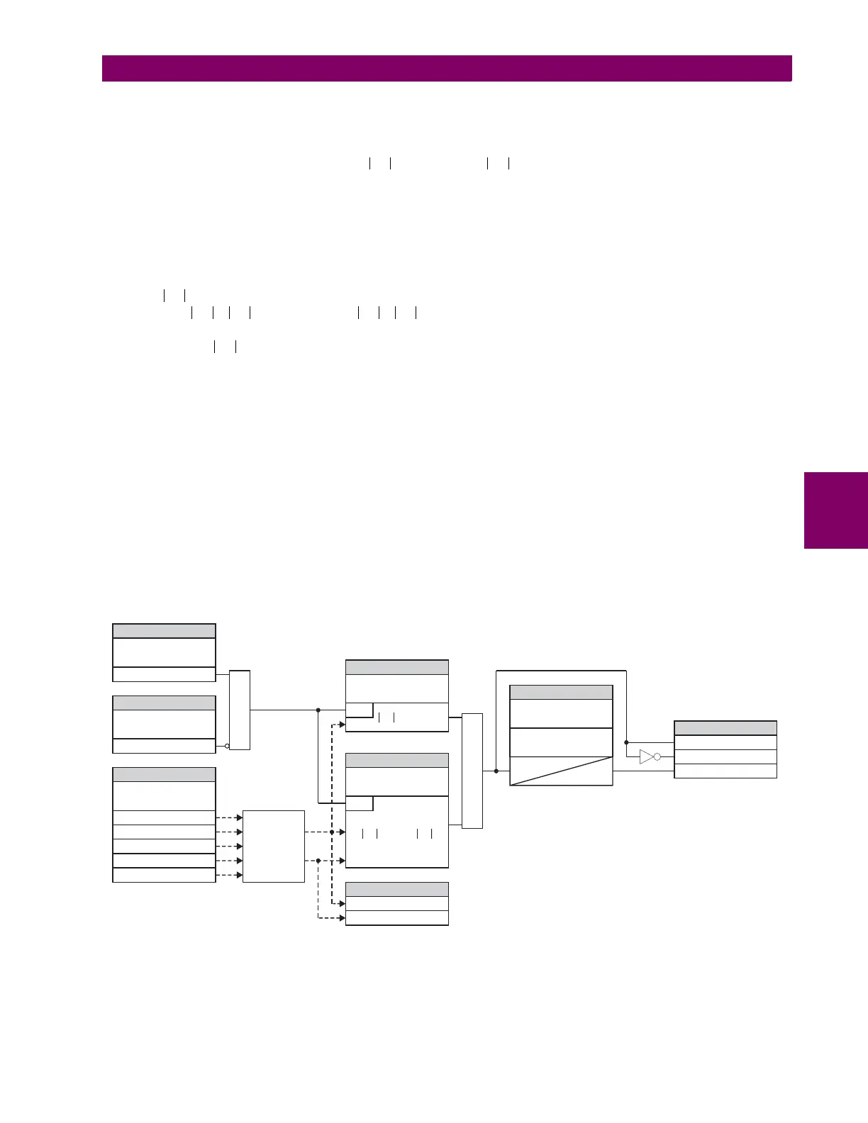
Having the differential and restraining signals developed, the element applies a single slope differential characteristic with a
minimum pickup as shown in the logic diagram below.
Figure 5–97: RESTRICTED GROUND FAULT SCHEME LOGIC
Igr k() max Irest k()α Igr k 1–()×,()=
SETTING
SETTING
SETTING
SETTING
SETTINGS
SETTING
FLEXLOGIC OPERANDS
ACTUAL VALUES
RESTD GND FT1
FUNCTION:
RESTD GND FT1
BLOCK:
RESTD GND FT1
SOURCE:
RESTD GND FT1
PICKUP:
RESTD GND FT1 RESET
DELAY:
RESTD GND FT1 PICKUP
DELAY:
RESTD GND FT1
SLOPE:
RESTD GND FT1 OP
RESTD GND FT1 DPO
RESTD GND FT1 PKP
RGF 1 Igd Mag
RGF 1 Igr Mag
Off=0
Enabled=1
AND
828002A3.CDR
RUN
RUN
Igd > PICKUP
IN
IG
I_0
I_1
I_2
AND
> SLOPE
*
Igd
Igr
Differential
and
Restraining
Currents
t
PKP
t
RST

 Loading...


