5-204 G60 Generator Protection System GE Multilin
5.6 GROUPED ELEMENTS 5 SETTINGS
5
The positive-sequence restraint must be considered when testing for pick-up accuracy and response time (multiple of
pickup). The positive-sequence restraint is removed for low currents. If the positive-sequence current is less than 0.8 pu,
then the restraint is removed by changing the constant K to zero. This results in better response to high-resistance faults
when the unbalance is very small and there is no danger of excessive CT errors, since the current is low.
The operating quantity depends on the way the test currents are injected into the G60. For single phase injection:
• I
op
= ⅓ × (1 – K)×I
injected
for I_2 mode.
• I
op
= (1 – K)×I
injected
for I_0 mode if I_1 > 0.8 pu.
The directional unit uses the negative-sequence current (I_2) and negative-sequence voltage (V_2).
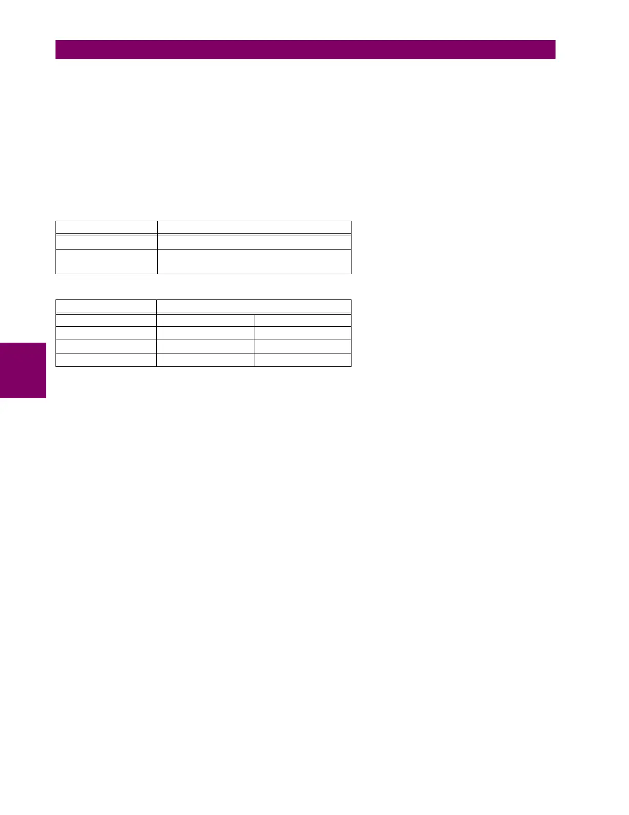
The following tables define the negative-sequence directional overcurrent element.
Table 5–29: NEGATIVE-SEQUENCE DIRECTIONAL OVERCURRENT UNIT
Table 5–30: NEGATIVE-SEQUENCE DIRECTIONAL UNIT
The negative-sequence voltage must be greater than the VOLTAGE CUTOFF LEVEL setting specified in the PRODUCT SETUP
DISPLAY PROPERTIES menu to be validated for use as a polarizing signal. If the polarizing signal is not validated neither
forward nor reverse indication is given. The following figure explains the usage of the voltage polarized directional unit of
the element.
The figure below shows the phase angle comparator characteristics for a phase A to ground fault, with settings of:
ECA = 75° (element characteristic angle = centerline of operating characteristic)
FWD LA = 80° (forward limit angle = ± the angular limit with the ECA for operation)
REV LA = 80° (reverse limit angle = ± the angular limit with the ECA for operation)
MODE OPERATING CURRENT
Negative-sequence I
op
= |I_2| – K × I_1|
Zero-sequence I
op
= 3 × (|I_0| – K × |I_1|) if |I_1| > 0.8 pu
I
op
= 3 × |I_0| if |I_1| ≤ 0.8 pu
DIRECTION COMPARED PHASORS
Forward –V_2 + Z_offset × I_2 I_2 × 1∠ECA
Reverse –V_2 + Z_offset × I_2 –(I_2 × 1∠ECA)
Forward –V_2 + Z_offset × I_2 I_2 × 1∠ECA
Reverse –V_2 + Z_offset × I_2 –(I_2 × 1∠ECA)

 Loading...


