GE Multilin G60 Generator Protection System 5-231
5 SETTINGS 5.6 GROUPED ELEMENTS
5
Figure 5–118: VOLTS PER HERTZ SCHEME LOGIC
The element has a linear reset characteristic. The reset time can be programmed to match the cooling characteristics of the
protected equipment. The element will fully reset from the trip threshold in VOLTS/HZ T-RESET seconds. The V/Hz element
may be used as an instantaneous element with no intentional time delay or as a Definite or Inverse timed element.
The characteristics of the inverse curves are shown below.
DEFINITE TIME:
For the definite time curve, T(sec.) = TD multiplier. For example, setting the TD multiplier to 20 results a time delay of 20
seconds to operate when above the Volts/Hz pickup setting. Instantaneous operation can be obtained the same way by
setting the TD multiplier to “0”.
INVERSE CURVE A:
The curve for the volts/hertz inverse curve A shape is derived from the formula:
(EQ 5.29)
where: T = Operating Time
TDM = Time Delay Multiplier (delay in seconds)
V = fundamental RMS value of voltage (pu)
F = frequency of voltage signal (pu)
Pickup = volts-per-hertz pickup setpoint (pu)
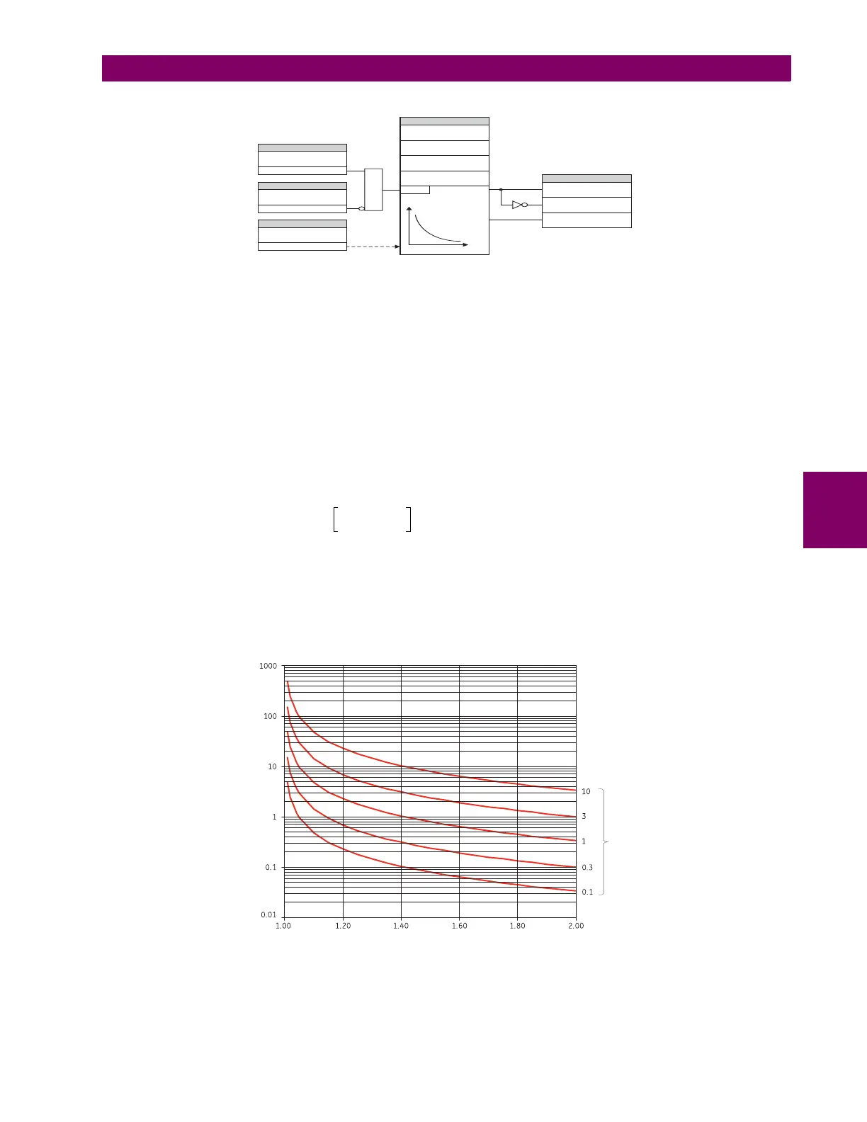
The volts/hertz inverse A curves are shown below.
Figure 5–119: VOLTS-PER-HERTZ CURVES, INVERSE CURVE A
SETTING
SETTINGS
FLEXLOGIC OPERANDS
SETTING
SETTING
VOLTS/HZ 1
FUNCTION:
VOLTS / HZ 1
TD MULTIPLIER:
VOLTS / HZ 1
T-RESET:
VOLTS / HZ 1
CURVE:
VOLTS / HZ 1
PICKUP:
VOLTS PER HERTZ 1 PKP
VOLTS PER HERTZ 1 DPO
VOLTS PER HERTZ 1 OP
VOLTS/HZ 1 BLOCK:
Off = 0
Enabled = 1
VOLTS/HZ 1
SOURCE:
VOLT / Hz
RUN
AND
t
V/Hz
828003A6.CDR
T
TDM
V
F
----
Pickup⁄
2
1–
-------------------------------------------------
when
V
F
----
Pickup>=
Multiples of volts per hertz pickup
Time to trip (in seconds)
Time
delay
setting
830738A1.CDR
 Loading...


