5-248 G60 Generator Protection System GE Multilin
5.6 GROUPED ELEMENTS 5 SETTINGS
5
The difference in angle can be used as the SH CT ANGLE COMPEN setting. The preferred method of doing this is by
inserting a resistance equal to the SH STATOR GND STG2 PICKUP setting at the neutral of the generator and compensat-
ing the angle at this setting.
• SH STATOR GND OC PICKUP: This setting specifies the backup overcurrent pickup level based on sub-harmonic cur-
rent. This protection can be used in addition to the sub-harmonic injection based 100% ground fault and fundamental
phasor over voltage based 95% ground fault protection. One per-unit value of current is the sensitive ground CT sec-
ondary rating setting, which is always 5 A since the CT used is rated for 5 A secondary.
• SH STATOR GND OC DELAY: This setting specifies a time delay for sub-harmonic current based backup over current
protection. Thermal capabilities of the loading resistor or neutral grounding transformer should be considered while
setting this delay.
• SH STATOR GND Vsupv: The 20 Hz source can be monitored using this voltage supervision. This setting in pu pro-
vides the voltage level below which if the sub-harmonic voltage phasor magnitude remains for a period of 10 seconds,
the
SH STAT GND TRB OP operand will be asserted. One per-unit value of voltage is the auxiliary VT nominal secondary
voltage setting or the equivalent primary voltage if used in primary. A typical setting of 1 V is suggested. However,
when the neutral grounding transformer’s load resistance is less than 0.5 ohms, the use of voltage supervision is not
recommended.
• SH STATOR GND Isupv: The 20 Hz source can be monitored using this current supervision. This setting in per-unit
values provides the current level below which if the sub-harmonic current phasor magnitude remains for a period of 10
seconds, the
SH STAT GND TRB OP operand will be asserted. One per-unit current is the sensitive ground CT second-
ary rating setting or the primary rating if used in primary. A typical setting of 0.002 pu (=10 mA in secondary) is recom-
mended with the provided 5 A secondary CT.
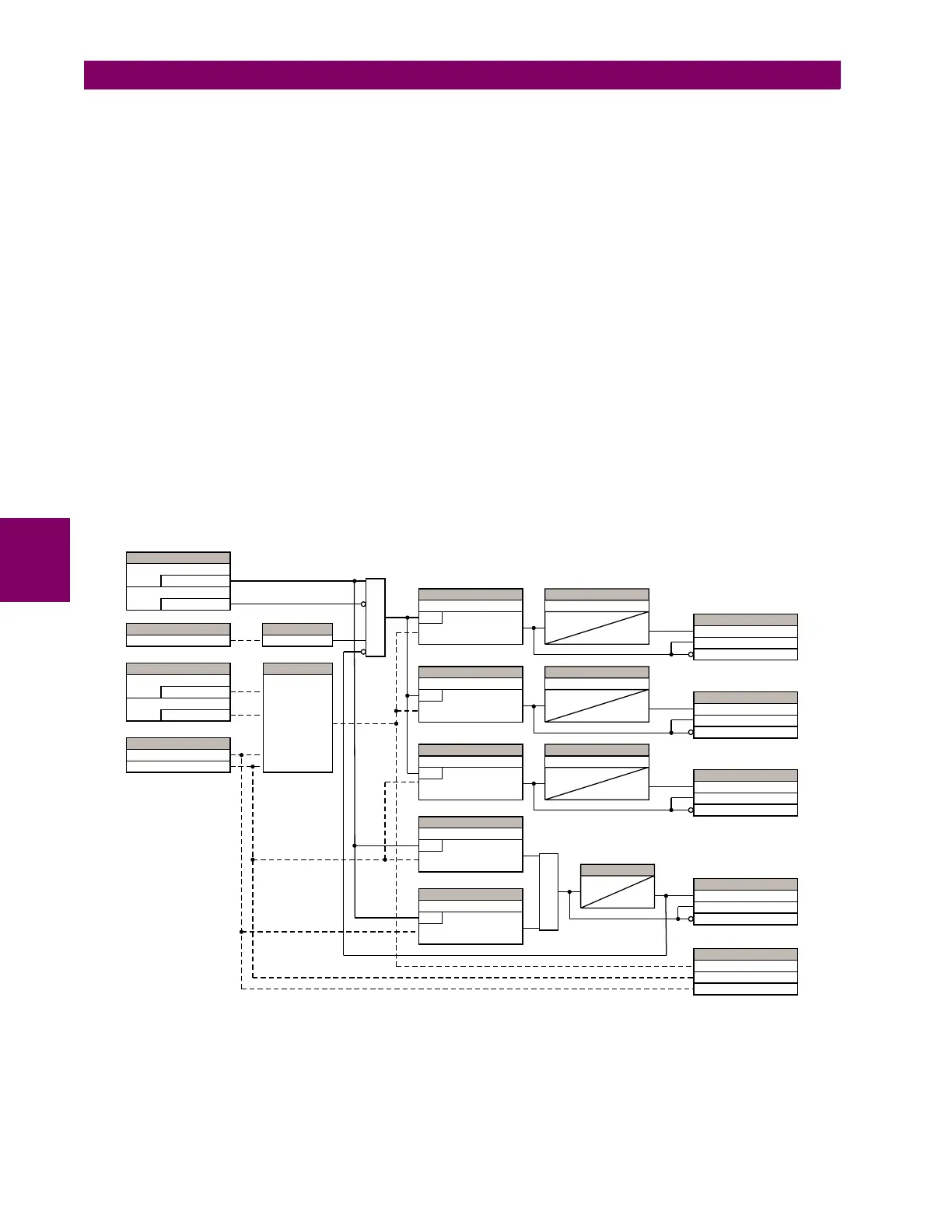
The logic for the sub-harmonic stator ground fault feature is shown below.
Figure 5–132: SUB-HARMONIC STATOR GROUND FAULT LOGIC
6(77,1*6
(QDEOHG
)XQFWLRQ
2II
%ORFN
$&78$/9$/8(
7UDFNLQJ)UHTXHQF\
&203$5$725
+]I+]
6(77,1*6
5V!
)XQFWLRQ
5S!
)XQFWLRQ
$&78$/9$/8(6
9DX[6+
,JQG6+
&$/&8/$7(
&DOFXODWH
UHVLVWDQFH
$1'
6(77,1*
6WDJH3LFNXS
581
5J3LFNXS
6(77,1*
6WDJH3LFNXS
581
5J3LFNXS
6(77,1*
*URXQG2&3LFNXS
581
,JQG3LFNXS
6(77,1*
&XUUHQW6XSHUYLVLRQ
581
,JQG3LFNXS
6(77,1*
9ROWDJH6XSHUYLVLRQ
581
9[3LFNXS
25
6(77,1*
6WDJH3LFNXS'HOD\
7
3.3
6(77,1*
6WDJH3LFNXS'HOD\
7
3.3
6(77,1*
*URXQG2&'HOD\
7
3.3
7,0(5
VHF
)/(;/2*,&23(5$1'6
6+67$725*1'67*23
6+67$725*1'67*3.3
6+67$725*1'67*'32
)/(;/2*,&23(5$1'6
6+67$725*1'67*23
6+67$725*1'67*3.3
6+67$725*1'67*'32
)/(;/2*,&23(5$1'6
6+67$725*1'2&23
6+67$725*1'2&3.3
6+67$725*1'2&'32
)/(;/2*,&23(5$1'6
6+67$725*1'75%23
6+67$725*1' 3.375%
6+67$725*1''3275%
$&78$/9$/8(6
6WDWRU*URXQG5HVLVWDQFH
6+,QMHFWLRQ$PSV
6+,QMHFWLRQ9ROWV
$&'5