5-250 G60 Generator Protection System GE Multilin
5.6 GROUPED ELEMENTS 5 SETTINGS
5
Measurement of R
G
is accomplished by injecting a voltage, V
INJ
and measuring the resulting current, I
G
. The measurement
algorithm must be capable of discriminating between capacitive current due to C
F
(which can be significant) and resistive
current due to a fault. The exciter voltage, V
FLD
is a DC value with a small ripple such that the impedance of the field is
essentially resistive. The current I
FLD
is a DC current with a range of tens, hundreds, or thousands of amps.
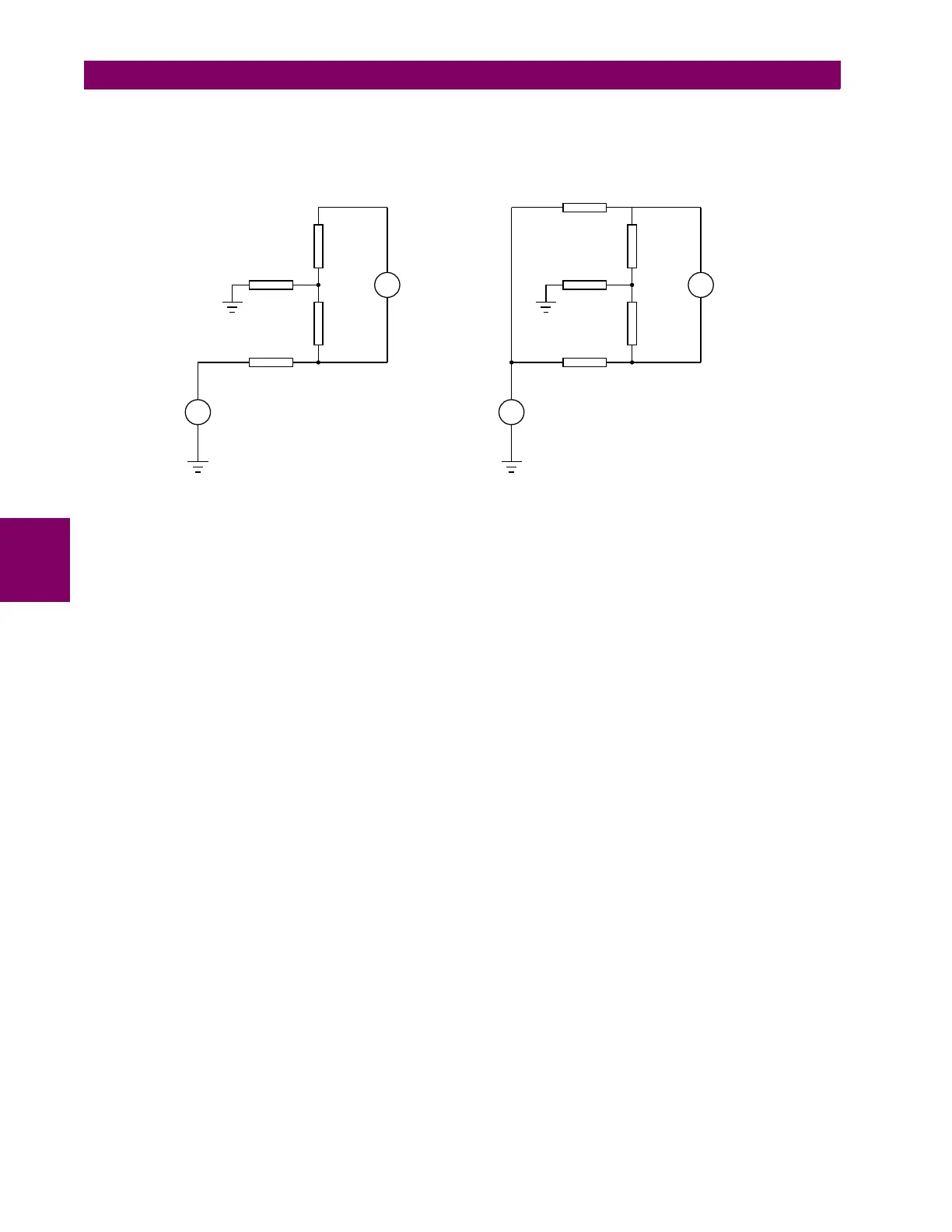
Figure 5–134: EQUIVALENT CIRCUIT, SINGLE-POINT AND DOUBLE-POINT INJECTION
Referring to the single-point injection circuit, the magnitude of I
FLD
makes it evident that V
INJ
cannot have a significant
impact on the voltage drop across Z
F2
. Therefore if two values (V
INJ1
and V
INJ2
) are injected the following equations can be
written:
(EQ 5.43)
Where I
G1
is the current flowing due to V
INJ1
and I
G2
is the current flowing due to V
INJ2
. Solving for R
G
we get:
(EQ 5.44)
For the double-point injection circuit, R
CL
is defined as:
(EQ 5.45)
The V
INJ
voltage is therefore composed of a square wave to create two levels of injection. Once the value of R
G
is known it
can be substituted into the V
INJ
equation above to determine V
F2
. If the V
FLD
voltage (refer to the single-point injection cir-
cuit) is known through measurement then the location of the fault is simply V
F2
/ V
FLD
. This gives the location of the fault as
percentage of field winding from negative terminal in case of single point injection. If double point injection is used, fault
location cannot be determined. The relay displays an invalid fault location for approximately 10% for such conditions. The
fault location cannot be determined if the field voltage is zero (that is, when the generator is not running). The fault location
is displayed only when the measured field ground resistance is less than 500 KΩ. Refer to Field Ground Module Instruction
Manual for details of wiring and installation.
GROUND UNDERCURRENT:
A brush lift-off condition will prevent the field ground detector from operating. This is detected by calculating the RMS value
of the ground current. It will normally have a nonzero value due to the capacitance of the field winding. A drop in this signal
indicates an open circuit in the injection path and the field ground under current feature detects this condition.
=
)
=
)
5
*
/2&
9
(;&
, ,
**
9 9
,1- ,1-
,
(;&
5
&/
$&'5
=
)
=
)
5
*
/2&
9
(;&
, ,
**
9 9
,1- ,1-
,
(;&
5
&
5
&
6LQJOHSRLQWLQMHFWLRQ'RXEOHSRLQWLQMHFWLRQ
V
INJ1
I
G1
R
G
I
G1
R
CL
V+
F2
+=
V
INJ2
I
G2
R
G
I
G2
R
CL
V+
F2
+=
R
G
V
INJ1
V
INJ2
–()I
G1
I
G2
–()R
CL
×–
I
G1
I
G2
–
------------------------------------------------------------------------------------------
=

 Loading...


