5-258 G60 Generator Protection System GE Multilin
5.7 CONTROL ELEMENTS 5 SETTINGS
5
The SETTING GROUPS BLK setting prevents the active setting group from changing when the FlexLogic parameter is set to
"On". This can be useful in applications where it is undesirable to change the settings under certain conditions, such as the
breaker being open.
The GROUP 2 ACTIVATE ON to GROUP 6 ACTIVATE ON settings select a FlexLogic operand which, when set, makes the partic-
ular setting group active for use by any grouped element. A priority scheme ensures that only one group is active at a given
time – the highest-numbered group that is activated by its
ACTIVATE ON parameter takes priority over the lower-numbered
groups. There is no activate on setting for group 1 (the default active group), because group 1 automatically becomes
active if no other group is active.
The SETTING GROUP 1 NAME to SETTING GROUP 6 NAME settings allows the user to assign a name to each of the six settings
groups. Once programmed, this name appears on the second line of the
GROUPED ELEMENTS SETTING GROUP 1(6) menu
display.
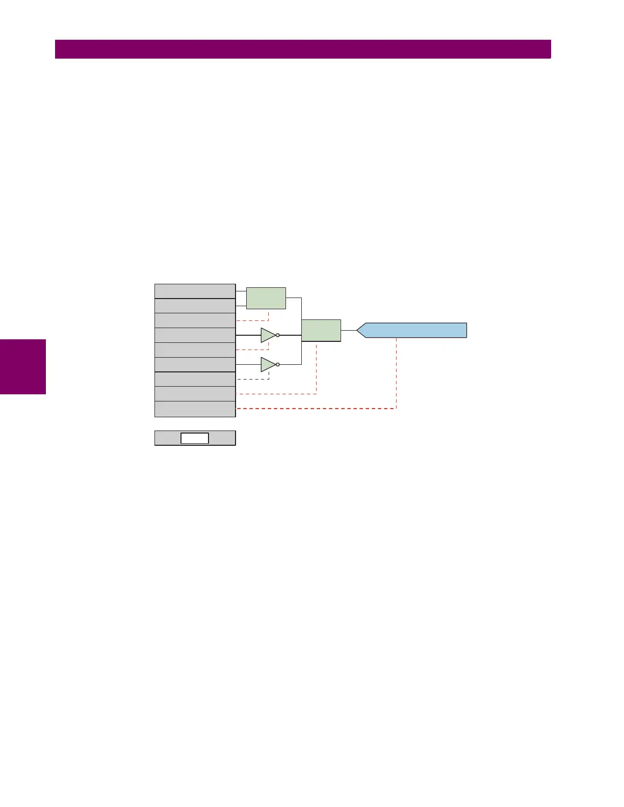
The relay can be set up via a FlexLogic equation to receive requests to activate or de-activate a particular non-default set-
tings group. The following FlexLogic equation (see the following figure) illustrates requests via remote communications (for
example, VIRTUAL INPUT 1 ON) or from a local contact input (for example, CONTACT IP 1 ON) to initiate the use of a particu-
lar settings group, and requests from several overcurrent pickup measuring elements to inhibit the use of the particular set-
tings group. The assigned
VIRTUAL OUTPUT 1 operand is used to control the “On” state of a particular settings group.
Figure 5–139: EXAMPLE FLEXLOGIC CONTROL OF A SETTINGS GROUP
10
1
VIRT IP 1 ON (VI1)
2
CONT IP 1 ON (H5A)
3
OR (2)
OR (2)
4
PHASE TOC1 PKP
5
NOT
6
PHASE TOC2 PKP
7
NOT
8
AND (3)
AND (3)
9
=VIRTOP1(VO1)
=VIRTOP1(VO1)
END
842789A1.CDR