GE Multilin G60 Generator Protection System 5-275
5 SETTINGS 5.7 CONTROL ELEMENTS
5
b) SPECIAL APPLICATION OF THE SYNCHROCHECK ELEMENT
The synchrocheck element is intended for applications where the potential sources are located on either side of the breaker
to be closed. It can also be used in cases where a power transformer is located between the two potential sources by com-
pensating for the power transformer phase shift with the auxiliary VT connection to the G60 and the auxiliary VT connection
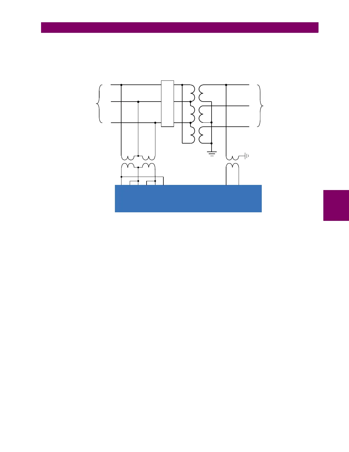
setting, as shown in the following example.
Figure 5–148: SYNCHROCHECK APPLIED ACROSS A TRANSFORMER
In this example, the phase voltage VT input is programmed as “Delta” with a secondary setting of 120 volts and a ratio of
13800 V/ 120 V = 115. The auxiliary VT connection is selected to be VAB since this vector is in phase with VA on the trans-
former primary. The secondary setting is 69 volts and the auxiliary VT ratio is calculated as 13800 V / 69 V = 200. Note that
the metered values for the auxiliary VT will now reflect the AB voltage of the secondary side of the transformer.
Phase VT input
A
B
C
a
b
c
System nominal
Vpp = 13.8 kV
System nominal
Vpp = 230 kV
138000 : 69
14400 : 120
~5a
52
~5c ~6a ~6c ~7a ~7c
~8a ~8c
Auxiliary VT input
UR-series device
843808A2.CDR